MODEL 54e pH/ORP | SECTION 6.0 |
| THEORY OF OPERATION |
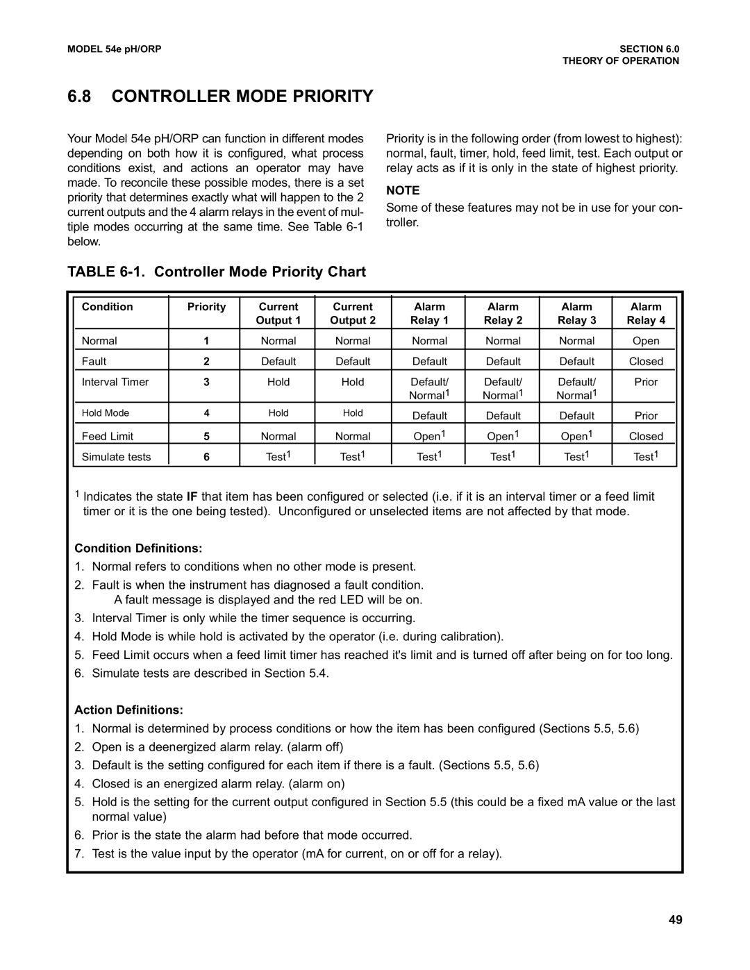
6.8CONTROLLER MODE PRIORITY
Your Model 54e pH/ORP can function in different modes depending on both how it is configured, what process conditions exist, and actions an operator may have made. To reconcile these possible modes, there is a set priority that determines exactly what will happen to the 2 current outputs and the 4 alarm relays in the event of mul- tiple modes occurring at the same time. See Table
Priority is in the following order (from lowest to highest): normal, fault, timer, hold, feed limit, test. Each output or relay acts as if it is only in the state of highest priority.
NOTE
Some of these features may not be in use for your con- troller.
TABLE 6-1. Controller Mode Priority Chart
| Condition | Priority | Current | Current | Alarm | Alarm | Alarm | Alarm | |
|
|
| Output 1 | Output 2 | Relay 1 | Relay 2 | Relay 3 | Relay 4 | |
|
|
|
|
|
|
|
|
|
|
| Normal | 1 | Normal | Normal | Normal | Normal | Normal | Open | |
|
|
|
|
|
|
|
|
|
|
| Fault | 2 | Default | Default | Default | Default | Default | Closed | |
|
|
|
|
|
|
|
|
|
|
| Interval Timer | 3 | Hold | Hold | Default/ | Default/ | Default/ | Prior | |
|
|
|
|
| Normal1 | Normal1 | Normal1 |
|
|
| Hold Mode | 4 | Hold | Hold | Default | Default | Default | Prior |
|
|
|
|
|
| |||||
| Feed Limit | 5 | Normal | Normal | Open1 | Open1 | Open1 | Closed |
|
| Simulate tests | 6 | Test1 | Test1 | Test1 | Test1 | Test1 | Test1 | |
1Indicates the state IF that item has been configured or selected (i.e. if it is an interval timer or a feed limit timer or it is the one being tested). Unconfigured or unselected items are not affected by that mode.
Condition Definitions:
1.Normal refers to conditions when no other mode is present.
2.Fault is when the instrument has diagnosed a fault condition. A fault message is displayed and the red LED will be on.
3.Interval Timer is only while the timer sequence is occurring.
4.Hold Mode is while hold is activated by the operator (i.e. during calibration).
5.Feed Limit occurs when a feed limit timer has reached it's limit and is turned off after being on for too long.
6.Simulate tests are described in Section 5.4.
Action Definitions:
1.Normal is determined by process conditions or how the item has been configured (Sections 5.5, 5.6)
2.Open is a deenergized alarm relay. (alarm off)
3.Default is the setting configured for each item if there is a fault. (Sections 5.5, 5.6)
4.Closed is an energized alarm relay. (alarm on)
5.Hold is the setting for the current output configured in Section 5.5 (this could be a fixed mA value or the last normal value)
6.Prior is the state the alarm had before that mode occurred.
7.Test is the value input by the operator (mA for current, on or off for a relay).
49