MODEL 54e pH/ORP | SECTION 5.0 |
| SOFTWARE CONFIGURATION |
5.7 CHANGING ALARM PARAMETERS (continued)
Interval Timer Setup
Timer: Disable
Timer: Time activated
Interval: 24.0 hr
ExitEdit
Repeats: 1
On time: 120 sec
Off time: 1 sec
ExitEdit
On time: 120 sec
Off time: 1 sec
Recovery: 600 sec
ExitEdit
7. | Menu Item | Options |
|
|
|
| Timer (enable) | Disable/AL1/AL2/AL3 |
|
|
|
| Interval | |
|
|
|
| Repeats | |
|
|
|
| On time | |
|
|
|
| Off time | |
|
|
|
| Recovery | |
|
|
|
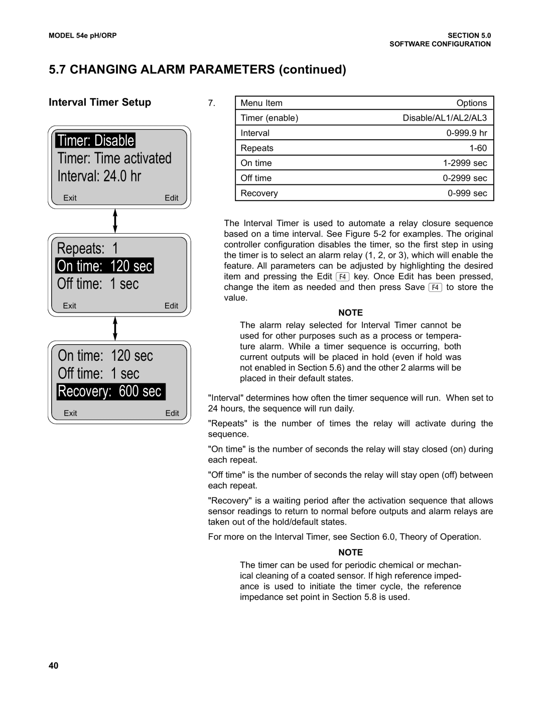
The Interval Timer is used to automate a relay closure sequence based on a time interval. See Figure
NOTE
The alarm relay selected for Interval Timer cannot be used for other purposes such as a process or tempera- ture alarm. While a timer sequence is occurring, both current outputs will be placed in hold (even if hold was not enabled in Section 5.6) and the other 2 alarms will be placed in their default states.
"Interval" determines how often the timer sequence will run. When set to 24 hours, the sequence will run daily.
"Repeats" is the number of times the relay will activate during the sequence.
"On time" is the number of seconds the relay will stay closed (on) during each repeat.
"Off time" is the number of seconds the relay will stay open (off) between each repeat.
"Recovery" is a waiting period after the activation sequence that allows sensor readings to return to normal before outputs and alarm relays are taken out of the hold/default states.
For more on the Interval Timer, see Section 6.0, Theory of Operation.
NOTE
The timer can be used for periodic chemical or mechan- ical cleaning of a coated sensor. If high reference imped- ance is used to initiate the timer cycle, the reference impedance set point in Section 5.8 is used.
40
