Operation
3.3.3Chilled Water Control
The chilled water control valve is adjusted proportionally as the temperature control varies the requirement for cooling from 0% to 100%. Units with the optional variable speed drive (VSD) control the fan speed in a similar manner, except that the minimum fan speed is 60% when the cooling requirement is less than 60%. Also, the fan is operated at 100% on a call for any heating and/or humidification.
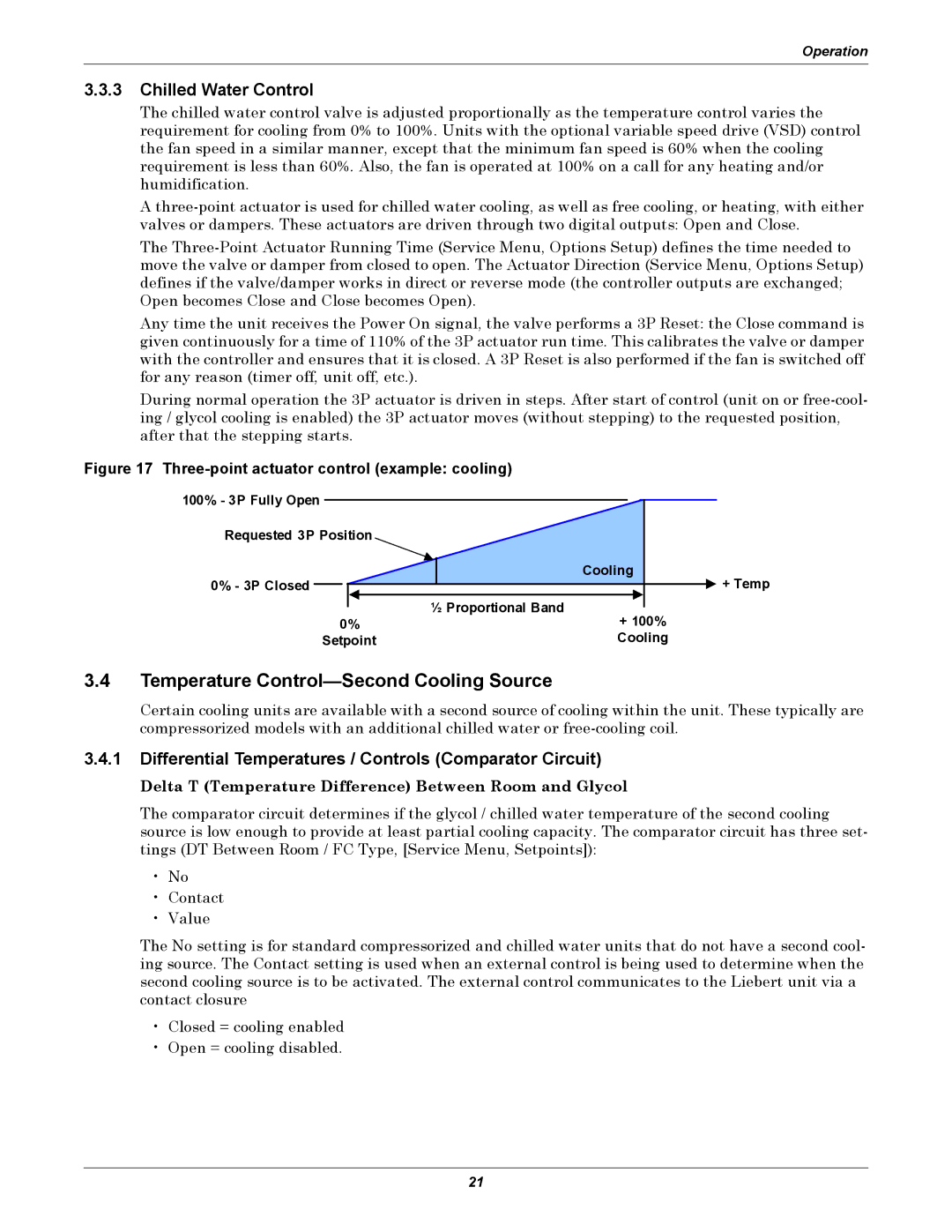
A
The
Any time the unit receives the Power On signal, the valve performs a 3P Reset: the Close command is given continuously for a time of 110% of the 3P actuator run time. This calibrates the valve or damper with the controller and ensures that it is closed. A 3P Reset is also performed if the fan is switched off for any reason (timer off, unit off, etc.).
During normal operation the 3P actuator is driven in steps. After start of control (unit on or
Figure 17 Three-point actuator control (example: cooling)
100% - 3P Fully Open |
|
Requested 3P Position |
|
| Cooling |
0% - 3P Closed | + Temp |
| ½ Proportional Band |
0% | + 100% |
Setpoint | Cooling |
3.4Temperature Control—Second Cooling Source
Certain cooling units are available with a second source of cooling within the unit. These typically are compressorized models with an additional chilled water or
3.4.1Differential Temperatures / Controls (Comparator Circuit)
Delta T (Temperature Difference) Between Room and Glycol
The comparator circuit determines if the glycol / chilled water temperature of the second cooling source is low enough to provide at least partial cooling capacity. The comparator circuit has three set- tings (DT Between Room / FC Type, [Service Menu, Setpoints]):
•No
•Contact
•Value
The No setting is for standard compressorized and chilled water units that do not have a second cool- ing source. The Contact setting is used when an external control is being used to determine when the second cooling source is to be activated. The external control communicates to the Liebert unit via a contact closure
•Closed = cooling enabled
•Open = cooling disabled.
21
