EMULEX MODEL 375 SAN STORAGE SWITCH | CHAPTER 2: SWITCH INSTALLATION |
USER’S GUIDE |
SWITCH LEDS
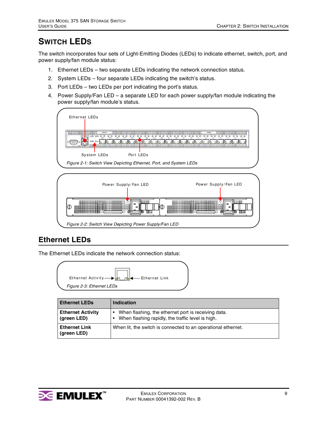
The switch incorporates four sets of
1.Ethernet LEDs – two separate LEDs indicating the network connection status.
2.System LEDs – four separate LEDs indicating the switch’s status.
3.Port LEDs – two LEDs per port indicating the port’s status.
4.Power Supply/Fan LED – a separate LED for each power supply/fan module indicating the power supply/fan module’s status.
Ethernet LEDs
System LEDs | Port LEDs |
Figure 2-1: Switch View Depicting Ethernet, Port, and System LEDs
Power Supply/Fan LED | Power Supply/Fan LED | ||
|
|
|
|
|
|
|
|
|
|
|
|
|
|
|
|
Figure 2-2: Switch View Depicting Power Supply/Fan LED
Ethernet LEDs
The Ethernet LEDs indicate the network connection status:
Ethernet Activity


 Ethernet Link
Figure 2-3: Ethernet LEDs
Ethernet LEDs | Indication | |
|
|
|
Ethernet Activity | • | When flashing, the ethernet port is receiving data. |
(green LED) | • | When flashing rapidly, the traffic level is high. |
|
| |
Ethernet Link | When lit, the switch is connected to an operational ethernet. | |
(green LED) |
|
|
|
|
|
EMULEX CORPORATION | 9 |
PART NUMBER