EMULEX MODEL 375 SAN STORAGE SWITCH | CHAPTER 3: SWITCH MANAGEMENT |
USER’S GUIDE |
In Figure
Note: When tape drives or tape libraries are included in multiple switch configurations incorporating multiple trunks, place the tape drive or tape library and any devices that access those devices on the secondary (duplicate) trunk, not the primary trunk.
Load balancing configuration settings are available on the Web Manager’s Load Balancing page. Before implementing load balancing on the switch, the automatic trunking settings must be configured. See “Automatic Trunking” on page 46 for additional information.
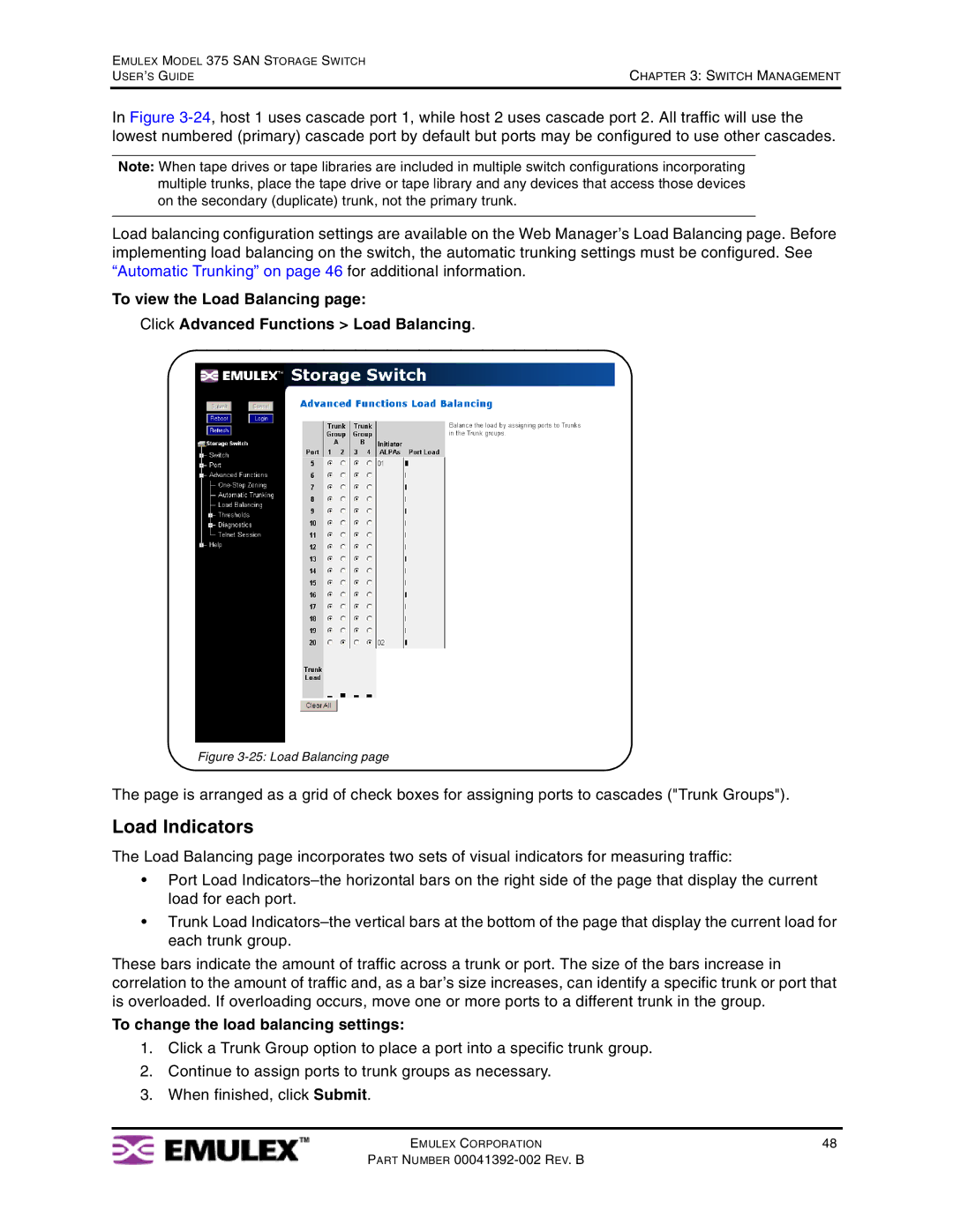
To view the Load Balancing page:
Click Advanced Functions > Load Balancing.
Figure 3-25: Load Balancing page
The page is arranged as a grid of check boxes for assigning ports to cascades ("Trunk Groups").
Load Indicators
The Load Balancing page incorporates two sets of visual indicators for measuring traffic:
•Port Load
•Trunk Load
These bars indicate the amount of traffic across a trunk or port. The size of the bars increase in correlation to the amount of traffic and, as a bar’s size increases, can identify a specific trunk or port that is overloaded. If overloading occurs, move one or more ports to a different trunk in the group.
To change the load balancing settings:
1.Click a Trunk Group option to place a port into a specific trunk group.
2.Continue to assign ports to trunk groups as necessary.
3.When finished, click Submit.
EMULEX CORPORATION | 48 |
PART NUMBER