DFE Module Placement and Installation Rules
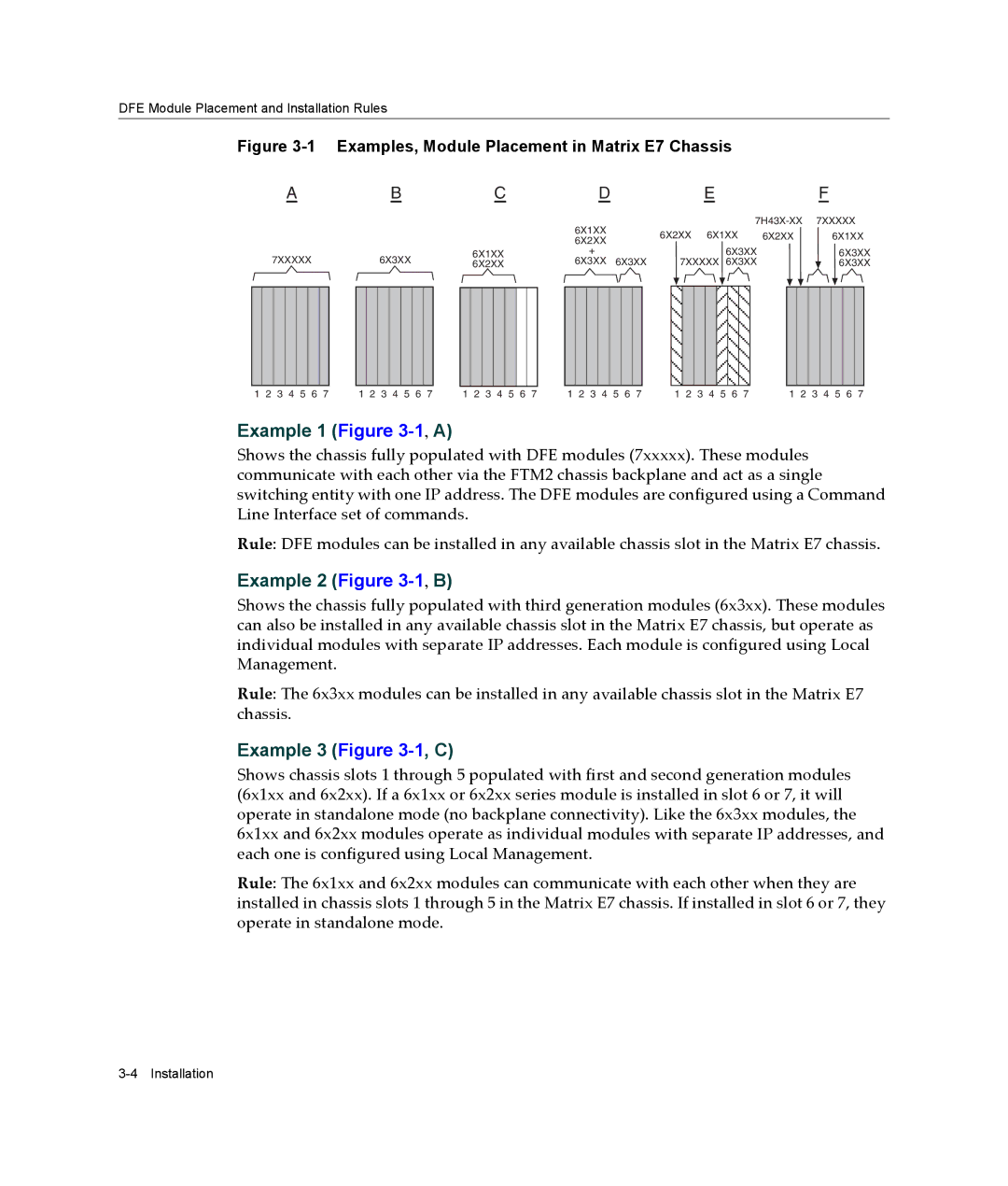
Figure 3-1 Examples, Module Placement in Matrix E7 Chassis
|
|
| A |
|
|
| B |
|
|
| C |
|
|
| D |
|
|
| E |
|
| F | |||||||||||||||||||||||
|
|
|
|
|
|
|
|
|
|
|
|
|
|
|
|
|
|
|
|
|
|
|
| 6X1XX |
|
|
|
|
|
|
|
| 7XXXXX | ||||||||||||
|
|
|
|
|
|
|
|
|
|
|
|
|
|
|
|
|
|
|
|
|
|
|
| 6X2XX 6X1XX | 6X2XX |
| 6X1XX | ||||||||||||||||||
|
|
|
|
|
|
|
|
|
|
|
|
|
|
|
|
|
|
|
|
|
|
|
| 6X2XX |
| ||||||||||||||||||||
| 7XXXXX |
|
| 6X3XX |
| 6X1XX | + |
|
|
|
|
|
|
|
|
|
| 6X3XX |
|
|
| 6X3XX | |||||||||||||||||||||||
|
|
|
| 6X2XX | 6X3XX 6X3XX |
| 7XXXXX 6X3XX |
|
|
| 6X3XX | ||||||||||||||||||||||||||||||||||
|
|
|
|
|
|
|
|
|
|
|
|
|
|
|
|
|
|
|
|
|
|
|
|
|
|
|
|
|
|
|
|
|
|
|
|
|
|
|
|
|
|
|
|
|
|
|
|
|
|
|
|
|
|
|
|
|
|
|
|
|
|
|
|
|
|
|
|
|
|
|
|
|
|
|
|
|
|
|
|
|
|
|
|
|
|
|
|
|
|
|
|
1 2 3 4 5 6 7 | 1 2 3 4 5 6 7 | 1 2 3 4 5 6 7 | 1 2 3 4 5 6 7 | 1 2 3 4 5 6 7 | 1 2 3 4 5 6 7 |
Example 1 (Figure 3-1, A)
Shows the chassis fully populated with DFE modules (7xxxxx). These modules communicate with each other via the FTM2 chassis backplane and act as a single switching entity with one IP address. The DFE modules are configured using a Command Line Interface set of commands.
Rule: DFE modules can be installed in any available chassis slot in the Matrix E7 chassis.
Example 2 (Figure 3-1, B)
Shows the chassis fully populated with third generation modules (6x3xx). These modules can also be installed in any available chassis slot in the Matrix E7 chassis, but operate as individual modules with separate IP addresses. Each module is configured using Local Management.
Rule: The 6x3xx modules can be installed in any available chassis slot in the Matrix E7 chassis.
Example 3 (Figure 3-1, C)
Shows chassis slots 1 through 5 populated with first and second generation modules (6x1xx and 6x2xx). If a 6x1xx or 6x2xx series module is installed in slot 6 or 7, it will operate in standalone mode (no backplane connectivity). Like the 6x3xx modules, the 6x1xx and 6x2xx modules operate as individual modules with separate IP addresses, and each one is configured using Local Management.
Rule: The 6x1xx and 6x2xx modules can communicate with each other when they are installed in chassis slots 1 through 5 in the Matrix E7 chassis. If installed in slot 6 or 7, they operate in standalone mode.