Gaining Access to Memory Modules
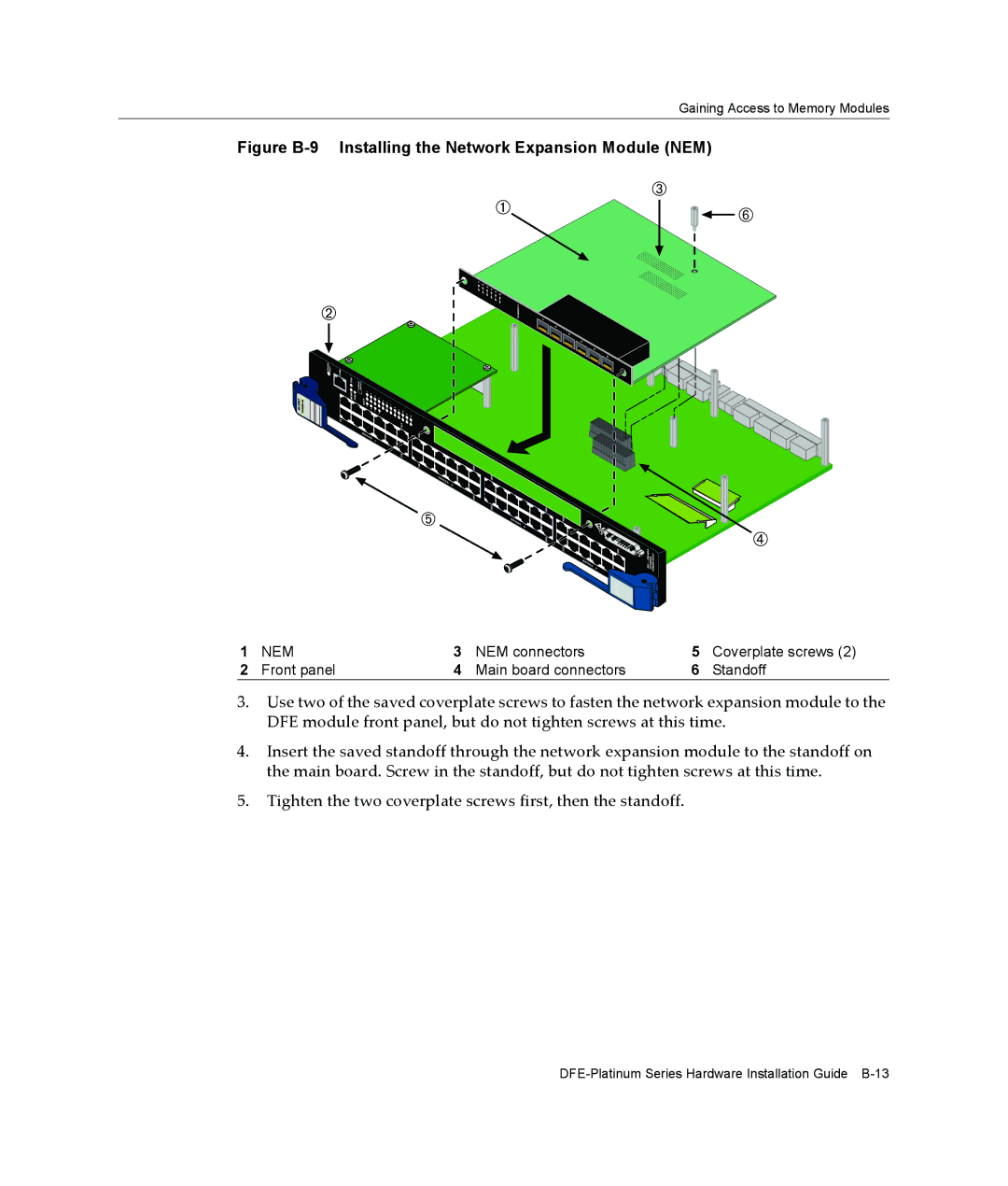
Figure B-9 Installing the Network Expansion Module (NEM)
1 | NEM | 3 | NEM connectors | 5 | Coverplate screws (2) |
2 | Front panel | 4 | Main board connectors | 6 | Standoff |
3.Use two of the saved coverplate screws to fasten the network expansion module to the DFE module front panel, but do not tighten screws at this time.
4.Insert the saved standoff through the network expansion module to the standoff on the main board. Screw in the standoff, but do not tighten screws at this time.
5.Tighten the two coverplate screws first, then the standoff.