Memory Locations and Replacement Procedures
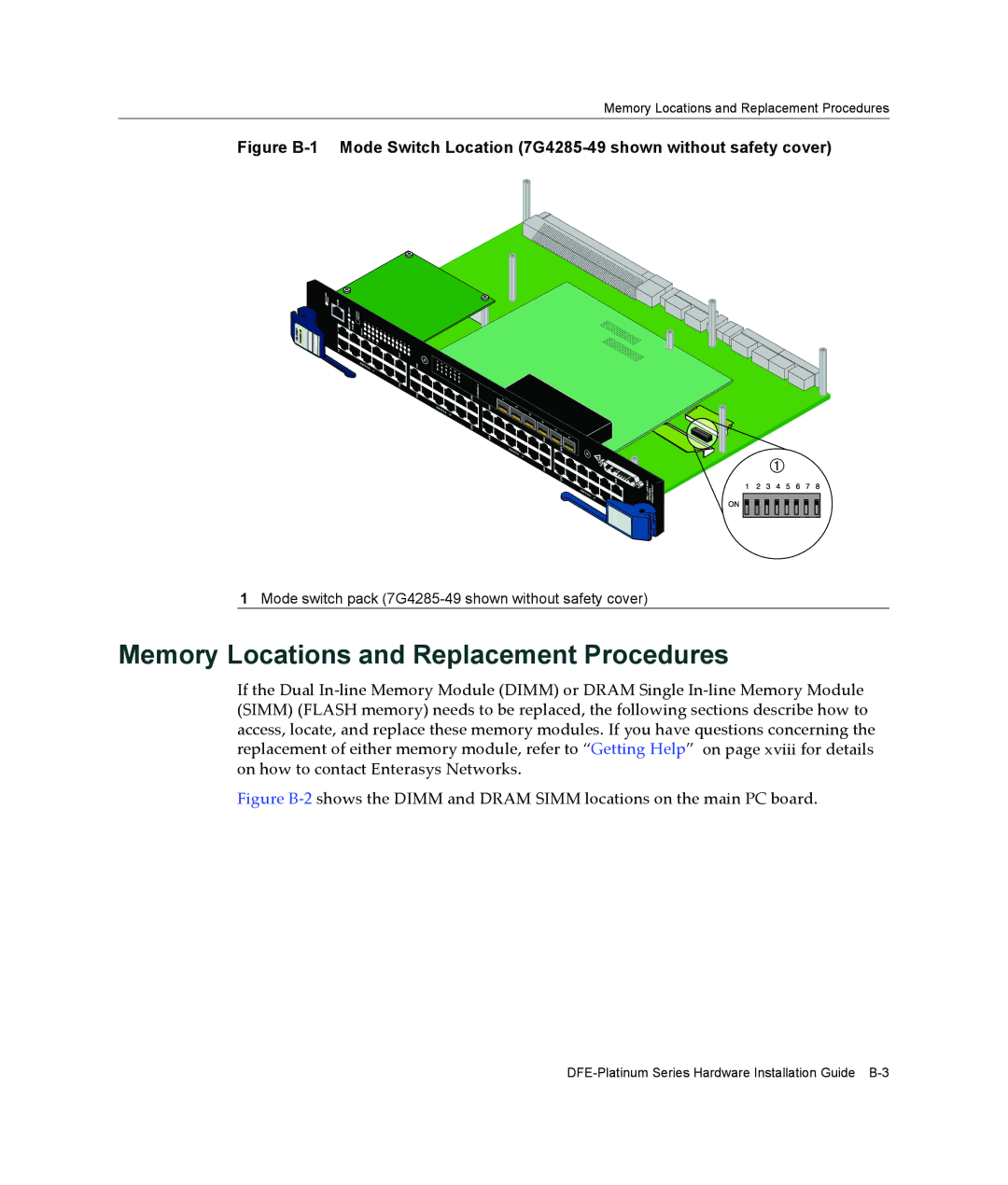
Figure B-1 Mode Switch Location (7G4285-49 shown without safety cover)
1Mode switch pack
Memory Locations and Replacement Procedures
If the Dual In‐line Memory Module (DIMM) or DRAM Single In‐line Memory Module (SIMM) (FLASH memory) needs to be replaced, the following sections describe how to access, locate, and replace these memory modules. If you have questions concerning the replacement of either memory module, refer to “Getting Help” on page xviii for details on how to contact Enterasys Networks.