Gaining Access to Memory Modules
4.Reinstall the safety cover. Refer to “Reinstalling the Safety Cover” on page B‐14 for instructions.
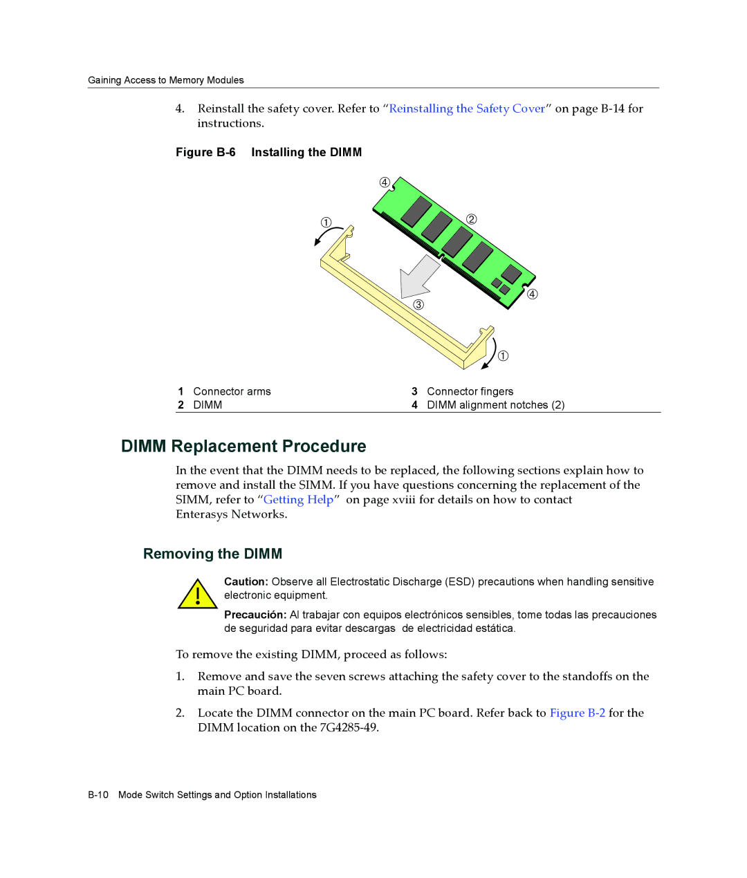
Figure B-6 Installing the DIMM
|
| Ã |
|
| À |
| Á |
|
| Â | Ã |
|
|
| |
|
|
| À |
1 | Connector arms | 3 | Connector fingers |
2 | DIMM | 4 | DIMM alignment notches (2) |
DIMM Replacement Procedure
In the event that the DIMM needs to be replaced, the following sections explain how to remove and install the SIMM. If you have questions concerning the replacement of the SIMM, refer to “Getting Help” on page xviii for details on how to contact Enterasys Networks.
Removing the DIMM
Caution: Observe all Electrostatic Discharge (ESD) precautions when handling sensitive electronic equipment.
Precaución: Al trabajar con equipos electrónicos sensibles, tome todas las precauciones de seguridad para evitar descargas de electricidad estática.
To remove the existing DIMM, proceed as follows:
1.Remove and save the seven screws attaching the safety cover to the standoffs on the main PC board.
2.Locate the DIMM connector on the main PC board. Refer back to Figure B‐2 for the DIMM location on the 7G4285‐49.