Gaining Access to Memory Modules
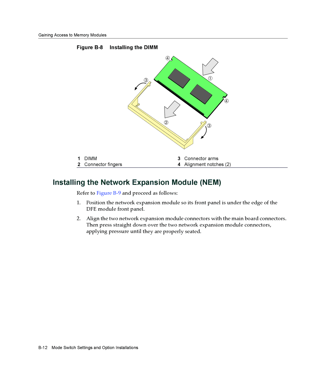
Figure B-8 Installing the DIMM
Ã
|
| Â | À |
|
|
| |
|
|
| Ã |
|
| Á | Â |
|
|
| |
1 | DIMM | 3 | Connector arms |
2 | Connector fingers | 4 | Alignment notches (2) |
Installing the Network Expansion Module (NEM)
Refer to Figure B‐9 and proceed as follows:
1.Position the network expansion module so its front panel is under the edge of the DFE module front panel.
2.Align the two network expansion module connectors with the main board connectors. Then press straight down over the two network expansion module connectors, applying pressure until they are properly seated.