Connecting to the Network
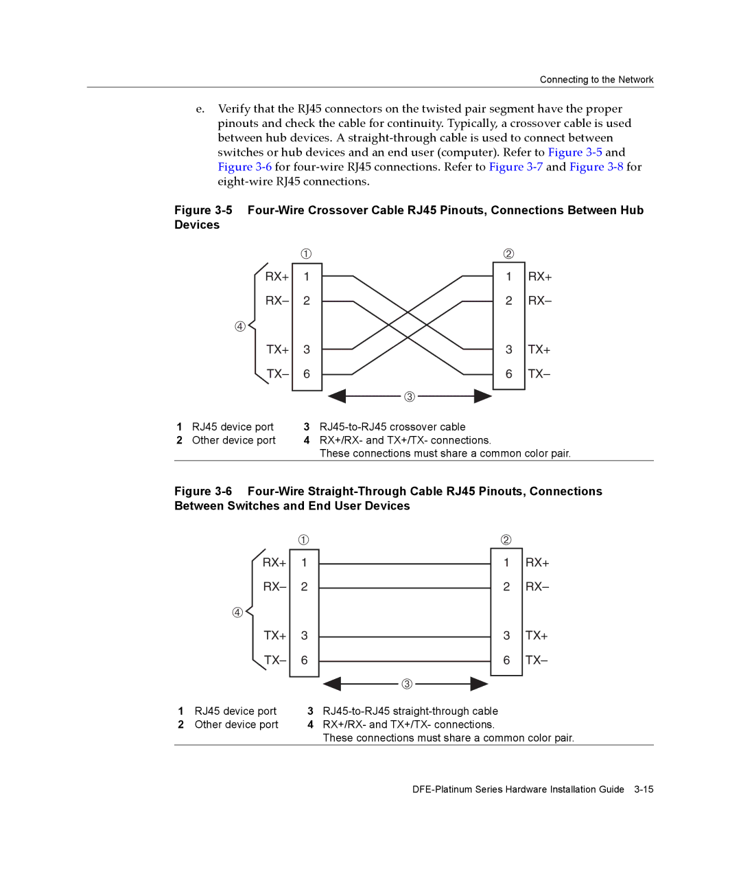
e.Verify that the RJ45 connectors on the twisted pair segment have the proper pinouts and check the cable for continuity. Typically, a crossover cable is used between hub devices. A straight‐through cable is used to connect between switches or hub devices and an end user (computer). Refer to Figure 3‐5 and Figure 3‐6 for four‐wire RJ45 connections. Refer to Figure 3‐7 and Figure 3‐8 for eight‐wire RJ45 connections.
Figure 3-5 Four-Wire Crossover Cable RJ45 Pinouts, Connections Between Hub Devices
| À |
RX+ | 1 |
RX– | 2 |
à |
|
TX+ | 3 |
TX– | 6 |
|
|
Â
Á
1RX+
2 RX–
3TX+
6 TX–
1 RJ45 device port 3
2 Other device port 4 RX+/RX- and TX+/TX- connections.
These connections must share a common color pair.
Figure 3-6 Four-Wire Straight-Through Cable RJ45 Pinouts, Connections Between Switches and End User Devices
ÀÁ
RX+ 1
RX– 2
Ã
TX+ 3
TX– 6
Â
1RX+
2 RX–
3TX+
6 TX–
1 | RJ45 device port | 3 | |
2 | Other device port | 4 | RX+/RX- and TX+/TX- connections. |
|
|
| These connections must share a common color pair. |