Preparing to Install into a Chassis
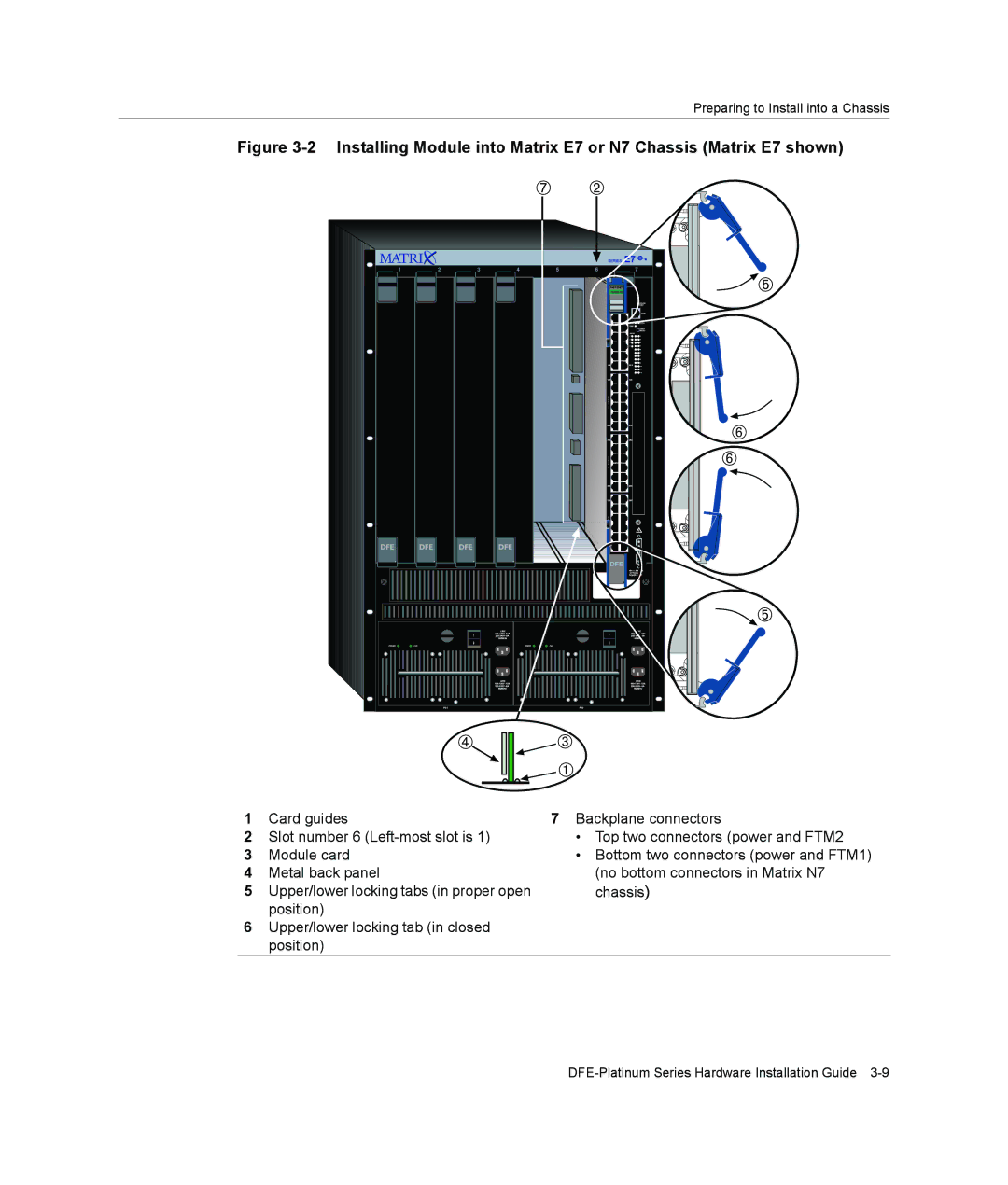
Figure 3-2 Installing Module into Matrix E7 or N7 Chassis (Matrix E7 shown)
1 | Card guides | 7 Backplane connectors |
2 | Slot number 6 | • Top two connectors (power and FTM2 |
3 | Module card | • Bottom two connectors (power and FTM1) |
4 | Metal back panel | (no bottom connectors in Matrix N7 |
5 | Upper/lower locking tabs (in proper open | chassis) |
| position) |
|
6Upper/lower locking tab (in closed position)