Gaining Access to Memory Modules
Removing the DIMM
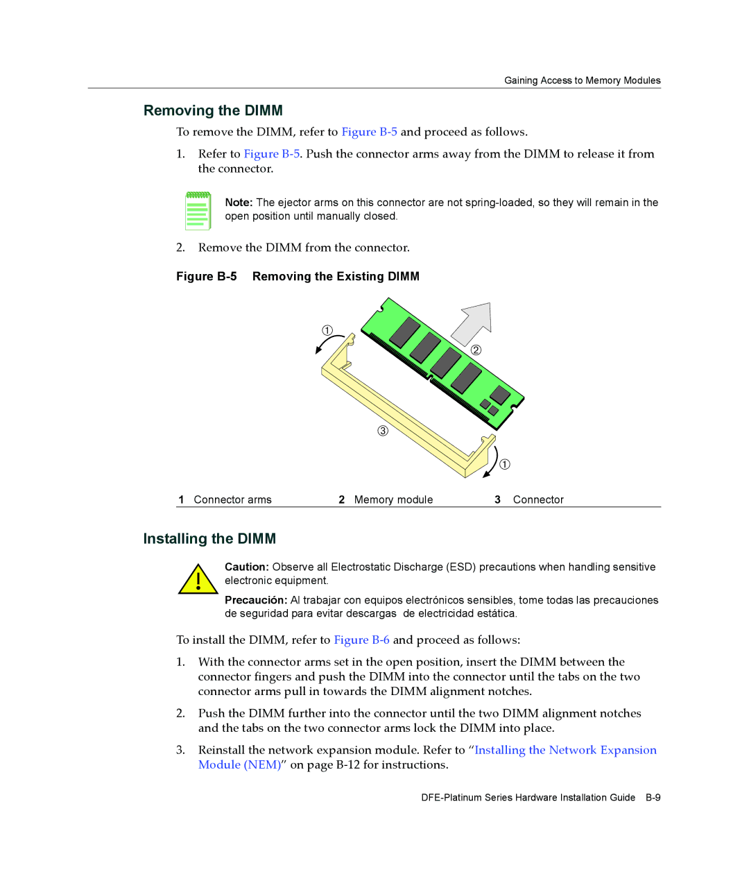
To remove the DIMM, refer to Figure B‐5 and proceed as follows.
1.Refer to Figure B‐5. Push the connector arms away from the DIMM to release it from the connector.
Note: The ejector arms on this connector are not
2.Remove the DIMM from the connector.
Figure B-5 Removing the Existing DIMM
À
![]() Á
Á
Â
![]() À
À
1 Connector arms | 2 Memory module | 3 Connector |
Installing the DIMM
Caution: Observe all Electrostatic Discharge (ESD) precautions when handling sensitive electronic equipment.
Precaución: Al trabajar con equipos electrónicos sensibles, tome todas las precauciones de seguridad para evitar descargas de electricidad estática.
To install the DIMM, refer to Figure B‐6 and proceed as follows:
1.With the connector arms set in the open position, insert the DIMM between the connector fingers and push the DIMM into the connector until the tabs on the two connector arms pull in towards the DIMM alignment notches.
2.Push the DIMM further into the connector until the two DIMM alignment notches and the tabs on the two connector arms lock the DIMM into place.
3.Reinstall the network expansion module. Refer to “Installing the Network Expansion Module (NEM)” on page B‐12 for instructions.