Gaining Access to Memory Modules
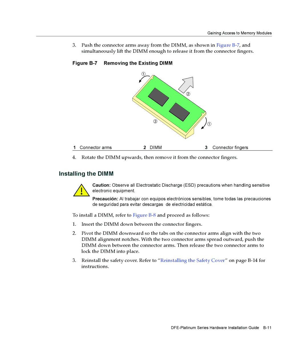
3.Push the connector arms away from the DIMM, as shown in Figure B‐7, and simultaneously lift the DIMM enough to release it from the connector fingers.
Figure B-7 Removing the Existing DIMM
À
Á
 ![]()
![]()
![]()
![]()
![]()
![]()
![]()
![]()
 À
À
1 Connector arms | 2 DIMM | 3 Connector fingers |
4.Rotate the DIMM upwards, then remove it from the connector fingers.
Installing the DIMM
Caution: Observe all Electrostatic Discharge (ESD) precautions when handling sensitive electronic equipment.
Precaución: Al trabajar con equipos electrónicos sensibles, tome todas las precauciones de seguridad para evitar descargas de electricidad estática.
To install a DIMM, refer to Figure B‐8 and proceed as follows:
1.Insert the DIMM down between the connector fingers.
2.Pivot the DIMM downward so the tabs on the connector arms align with the two DIMM alignment notches. With the two connector arms spread outward, push the DIMM down between the connector arms. Then release the two connector arms to lock the DIMM into place.
3.Reinstall the safety cover. Refer to “Reinstalling the Safety Cover” on page B‐14 for instructions.