Connecting to the Network
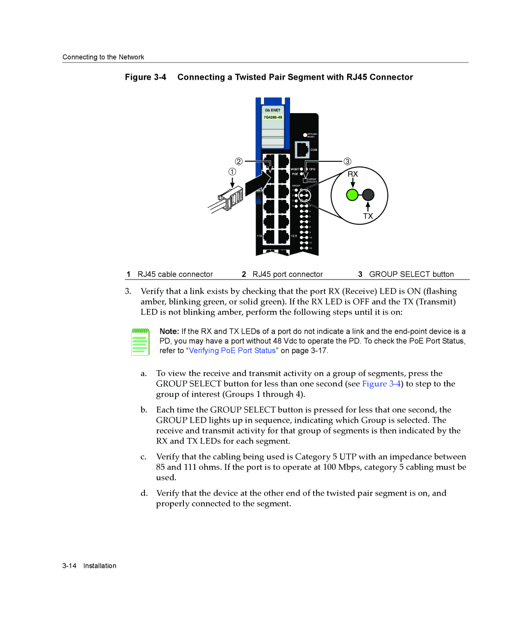
Figure 3-4 Connecting a Twisted Pair Segment with RJ45 Connector
| Gb ENET |
|
|
|
|
| |
|
| OFFLINE/ |
|
|
| RESET |
|
|
| COM |
|
Á |
|
| Â |
À | MGMT | CPU | RX |
POE | GROUP | ||
|
|
| |
|
| SELECT |
|
| GROUP |
|
|
| 1 | 1 |
|
| 2 | 2 |
|
| 3 | 3 |
|
1 | 4 | 4 |
|
|
| 5 | TX |
|
| 6 | |
|
| 7 |
|
|
| 8 |
|
|
| 9 |
|
11X | 12 X | 10 |
|
|
|
| |
|
| 11 |
|
|
| 12 |
|
1 RJ45 cable connector | 2 RJ45 port connector | 3 GROUP SELECT button |
3.Verify that a link exists by checking that the port RX (Receive) LED is ON (flashing amber, blinking green, or solid green). If the RX LED is OFF and the TX (Transmit) LED is not blinking amber, perform the following steps until it is on:
Note: If the RX and TX LEDs of a port do not indicate a link and the
a.To view the receive and transmit activity on a group of segments, press the GROUP SELECT button for less than one second (see Figure 3‐4) to step to the group of interest (Groups 1 through 4).
b.Each time the GROUP SELECT button is pressed for less that one second, the GROUP LED lights up in sequence, indicating which Group is selected. The receive and transmit activity for that group of segments is then indicated by the RX and TX LEDs for each segment.
c.Verify that the cabling being used is Category 5 UTP with an impedance between 85 and 111 ohms. If the port is to operate at 100 Mbps, category 5 cabling must be used.
d.Verify that the device at the other end of the twisted pair segment is on, and properly connected to the segment.