Installation, cont’d
RGBHV input and output
The switcher can connect to up to as many as 16 RGBHV video and/or stereo audio devices, depending on the model. The switcher can output to as many as 16 video and/or audio outputs, depending on the model.
The CrossPoint Series switchers can also switch RGBS, RGsB, RsGsBs, component video,
If switching a video format other than RGBHV, ensure that the same video planes (R, G, B, H/HV, and/or V) are used on the switcher output as on the input.
The switchers do not alter the video signal in any way. The signal output by the switcher is in the same format as the input.
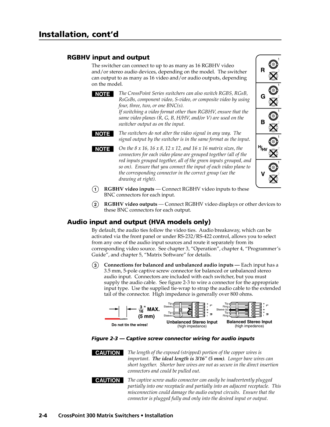
On the 8 x 16, 16 x 8, 12 x 12, and 16 x 16 matrix sizes, the connectors for each video plane are grouped together (all of the red inputs grouped together, all of the green inputs grouped, and so on). Ensure that you connect the input of each video plane to the corresponding connector in the correct group (see the drawing at right).
1RGBHV video inputs — Connect RGBHV video inputs to these BNC connectors for each input.
1
2
1
2
1
2
1
2
1
2
2RGBHV video outputs — Connect RGBHV video displays or other devices to these BNC connectors for each output.
Audio input and output (HVA models only)
By default, the audio ties follow the video ties. Audio breakaway, which can be activated via the front panel or under
3Connections for balanced and unbalanced audio inputs — Each input has a 3.5 mm,
Tip |
Sleeve |
Tip |
Sleeve |
L | Tip | |
Ring | ||
| ||
| Sleeve (s) | |
R | Tip | |
Ring | ||
|
![]() L R
L R
Do not tin the wires! | Unbalanced Stereo Input | Balanced Stereo Input | |
(high impedance) | (high impedance) | ||
|
Figure 2-3 — Captive screw connector wiring for audio inputs
CAUTION
CAUTION
The length of the exposed (stripped) portion of the copper wires is important. The ideal length is 3/16" (5 mm). Longer bare wires can short together. Shorter bare wires are not as secure in the direct insertion connectors and could be pulled out.
The captive screw audio connector can easily be inadvertently plugged partially into one receptacle and partially into an adjacent receptacle. This misconnection could damage the audio output circuits. Ensure that the connector is plugged fully and only into the desired input or output.