CrossPoint 300 Series
Matrix Switchers
Instrucciones de seguridad Español
Safety Instructions English
Consignes de Sécurité Français
Sicherheitsanleitungen Deutsch
CrossPoint 300 Matrix Switchers Quick Start QS-1
Quick Start CrossPoint 300 Matrix Switchers
QS-2 CrossPoint 300 Matrix Switchers Quick Start
Quick Start CrossPoint 300 Matrix Switchers, cont’d
Save or recall a preset
View, adjust the audio level
Table of Contents
Table of Contents, cont’d
CrossPoint 300 Matrix Switchers Table of Contents Iii
Iv CrossPoint 300 Matrix Switchers Table of Contents
One
About this Manual
About the Matrix Switchers
CrossPoint 300 Matrix Switchers Introduction
Introductiontroduction, cont’d
Extron CrossPoint 300 128 HVA
Definitions
Introduction, cont’d
Features
CrossPoint 300 Matrix Switchers Introduction
This page was intentionally left blank
Two
UL requirements
Installationstallation, cont’d
Mounting the Switcher
CrossPoint 300 Matrix Switchers Installation
Shows the CrossPoint 300 128 HVA
Connections and Rear Panel Features
Rgbhv input and output
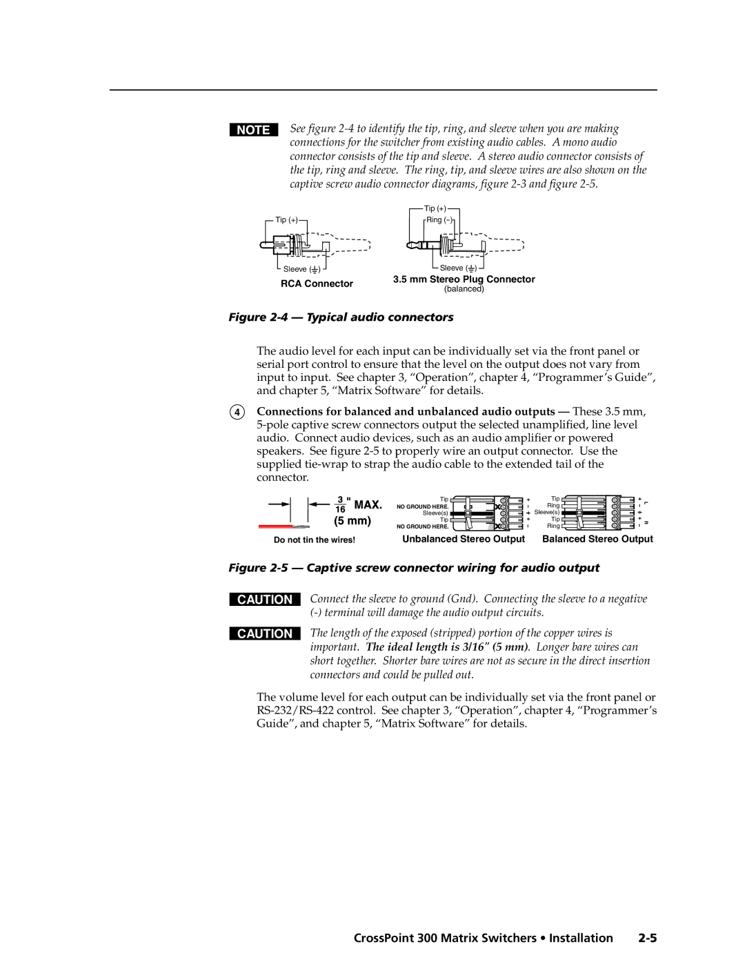
Installation, cont’d
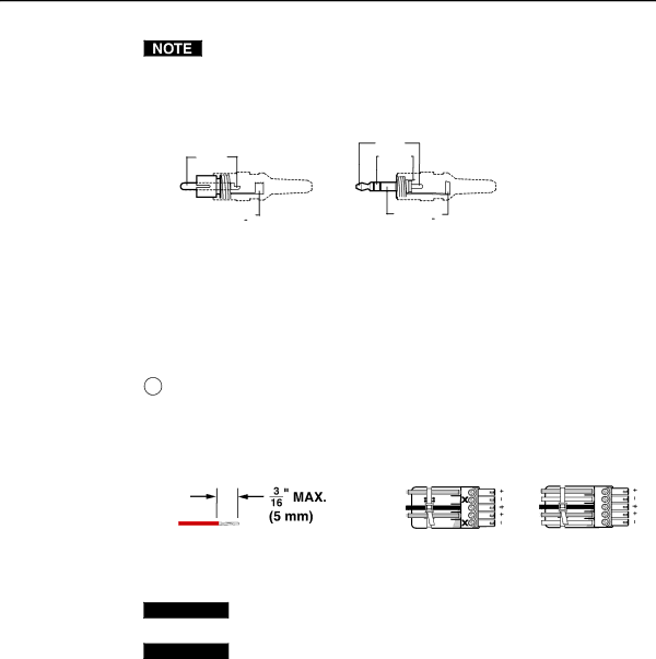
Audio input and output HVA models only
Typical audio connectors
Remote RS-232/RS-422 port
Reset button
Power
Sync termination switches
Front panel configuration port
Front Panel Configuration Port
CrossPoint 300 Matrix Switchers Installation
Installation, cont’d
Three
CrossPoint 300 Matrix Switchers Operation
Front Panel Controls and Indicators
Operationeration, cont’d
Input and output buttons
Definitions
Control buttons
Operation, cont’d
CrossPoint 300 Matrix Switchers Operation
Controls
Front panel security lockouts
Front Panel Operations
Creating a configuration
Power indications
Clear all selections
Example 1 Creating a set of video and audio ties
Example 2 Adding a tie to a set of video and audio ties
Press and release the Enter button figure
10 Clear all selections
Example 3 Removing a tie from a set of video and audio ties
Press and release the Enter button figure
16 Clear all selections
19 Deselect the output
22 Clear all selections
Viewing a configuration
23 Select Rgbhv or video and audio
25 Deselect Rgbhv to view audio ties only
Example 5 Muting and unmuting an output
Muting and unmuting video and/or audio
29 Select Rgbhv and audio
31 Unmute the outputs
Using global presets
LED blinks figure
Example 6 Saving a preset
Press and release the Preset button figure
Example 7 Recalling a preset
39 Select the preset
CrossPoint 300 Series Switcher
Viewing and adjusting the input audio level HVA models
42 Clear all selections
Example 8 Viewing and adjusting an input audio level
Audio gain and attenuation settings
45 Level display on a 16-output-LED switcher
46 Adjust the input audio level
Press and release the Audio button figure
Viewing and adjusting the output volume HVA models
Reading the displayed value
Push Esc button nineteen times 10% + 191.5% = 38.5% volume
Audio output volume settings
49 Clear all selections
Example 9 Viewing and adjusting an output volume level
51 Select output
54 Volume display on a 16-output-button switcher
Setting the front panel locks Executive modes
56 Toggle front panel lock on or off
Selecting Lock mode 2 or toggling between mode 2 and mode
Power
Performing a system reset from the front panel
Selecting the rear panel Remote port protocol and baud rate
Control Control I/O Enter Preset View ESC Rgbhv Audio
60 RS-232/RS-422 and baud rate selection
Rear Panel Operations
Performing a system reset from the rear panel
Performing a hard reset from the rear panel
Optimizing the Audio HVA Switchers
Plasma display S-video problem
Troubleshooting
General checks
Worksheet example 1 Entering system equipment
Configuration Worksheets
Worksheet example 2 Drawing ties
65 Worksheet example 2 Status meeting configuration
66 Worksheet example 3 Test configuration
Worksheet example 3 Test configuration
Preset #
Matrix Switchers Configuration Worksheet
This page was intentionally left blank
Four
Rear panel Remote port
CrossPoint 300 Matrix Switchers Programmer’s Guide
Programmer’ser’sGuide,Guidecont’d
Serial Ports
Front panel Configuration port
Host-to-Switcher Instructions
Programmer’s Guide, cont’d
Switcher-Initiated Messages
Using the Command/Response Table
Switcher Error Responses
Symbol Definitions
Command/Response Table for SIS Commands
Command Ascii Command Response Additional description
Command/response table for SIS commands
Command/response table for SIS commands Cont’d
Audio volume adjustment settings
Save, recall, and directly write presets
Response Additional description
Command
Serial port configuration
Five
MatrixSoftware,cont’d
Matrix Switchers Control Program
Installing the software
CrossPoint 300 Matrix Switchers Matrix Software
Comm port selection window
Using the software
Matrix Software, cont’d
Extron Matrix Switchers Control Program window no ties
Sample program window with ties
Updating the firmware
Open window
CrossPoint 300 Matrix Switchers Matrix Software
Windows menus
Windows buttons, drop boxes, and trash
File menu
Status window
Tools menu
Preferences menu
Audio-input Configure selection
Using the help system
Using emulation mode
Button-Label Generator
13 Extron’s Button-Label Generator window
AAppendix a
CrossPoint 300 Matrix Switchers Reference Information
Specifications
ReferenceInformation,co t’d
Sync
Reference Information, cont’d
Control/remote switcher
Included parts
Optional accessories
Part Numbers
CrossPoint 300 part numbers
Button Labels
Figure A-1 Button label blanks, 16-button strips
Reference Information, cont’d
FCC Class a Notice Extron’s Warranty
Extron Electronics, Europe Beeldschermweg 6C