Installationstallation, cont’d
Mounting the Switcher
The IN1508 comes with rubber feet and a set of rack mounting brackets.
Tabletop use
Attach a
Rack mounting
UL requirements
The following Underwriters Laboratories (UL) requirements pertain to the installation of the switcher into a rack (figure
1. Elevated operating ambient temperature — If installed in a closed or multi- unit rack assembly, the operating ambient temperature of the rack environment may be greater than room ambient temperature. Therefore, install the MLC in an environment compatible with the maximum ambient temperature (Tma = +122 °F, +50 °C) specified by Extron.
2. Reduced air flow — Install the equipment in a rack so that the amount of air flow required for safe operation of the equipment is not compromised.
3. Mechanical loading — Mount the equipment in the rack so that a hazardous condition is not achieved due to uneven mechanical loading.
4. Circuit overloading — Connect the equipment to the supply circuit and consider the effect that circuit overloading might have on overcurrent protection and supply wiring. Appropriate consideration of equipment nameplate ratings should be used when addressing this concern.
5.Reliable earthing (grounding) — Maintain reliable grounding of rack- mounted equipment. Pay particular attention to supply connections other than direct connections to the branch circuit (e.g. use of power strips).
Mounting instructions
Rack mount the switcher as follows:
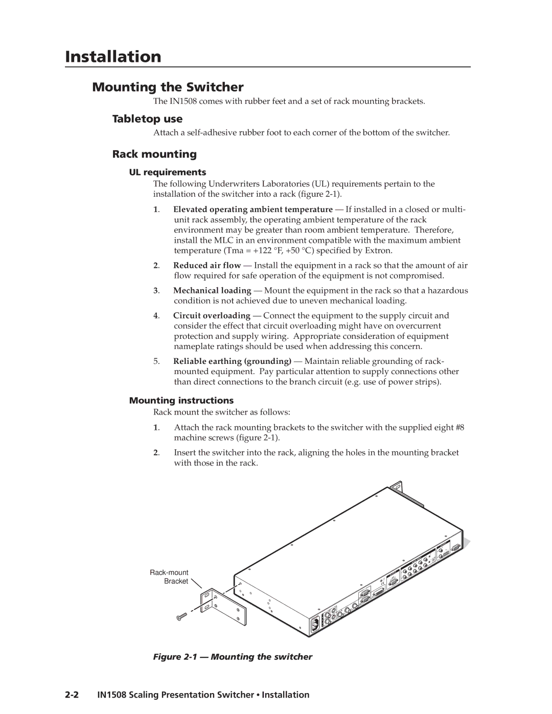
1. | Attach the rack mounting brackets to the switcher with the supplied eight #8 |
| machine screws (figure |
2. | Insert the switcher into the rack, aligning the holes in the mounting bracket |
| with those in the rack. |
![]()
|
|
| OUTPUT |
|
|
| A |
|
|
| B |
|
|
| L |
|
| 6 |
|
|
| 5 | R |
| INPUT4 | 8 | |
| 7 |
| |
AUD | IO |
|
|
3 |
|
|
2
OUTPUT | L |
|
RGB | ||
Y, B | R | |
|
| |
| 6 |
RGB | DVI |
| |
| 7 |
RGB |
|
| 3 | YC | |
|
|
| |
1 | VID |
| 5 |
I |
|
| |
|
|
| |
N | VID | Y |
|
P | 4 |
|
|
U |
|
|
|
2 |
|
|
|
T |
|
|
|