IN1508
Precautions
FCC Class a Notice
Quick Start IN1508 Scaling Presentation Switcher
Front Panel Controls
Table of Contents
Table of Contents, cont’d
IN1508 Scaling Presentation Switcher Table of Contents Iii
Iv IN1508 Scaling Presentation Switcher Table of Contents
One
Introductiontroduction, cont’d
DVI video
IN1508 Scaling Presentation Switcher Introduction
Standard DVI cable
Features
IN9700 cable
IN1508 Scaling Presentation Switcher Introduction
Introduction, cont’d
IN1508 Scaling Presentation Switcher Introduction
Introduction, cont’d
Two
Tabletop use
Mounting the Switcher
Rack mounting
Cabling and Rear Panel Views
Power connection
Video connections
Audio connections
Installation, cont’d
Configuration
Remote Control Battery Installation
RS-232 connection
Installation, cont’d
Three
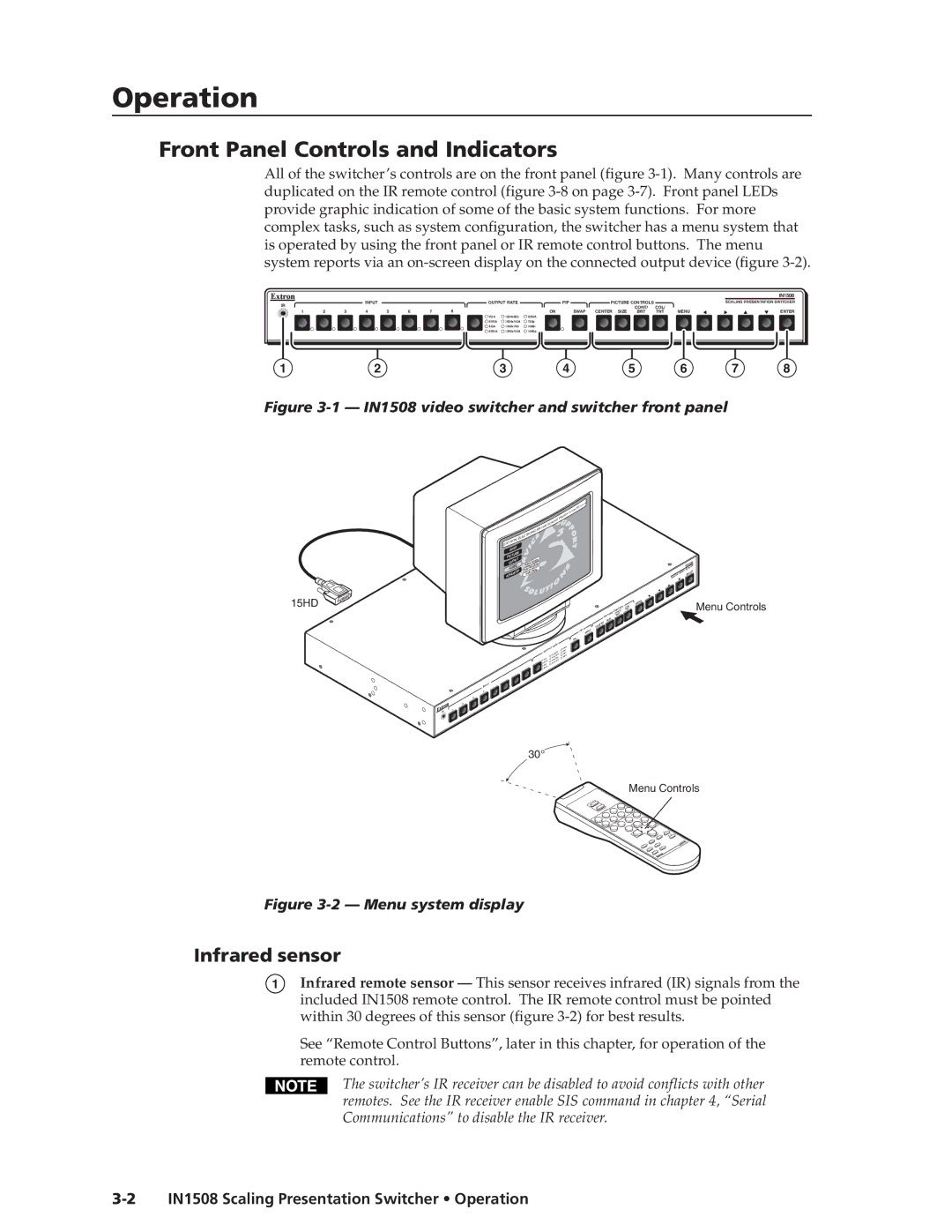
IN1508 Scaling Presentation Switcher Operation
Front Panel Controls and Indicators
Infrared sensor
Input selection buttons and LEDs
Input controls
Output Rate selection
Operation, cont’d
PIP buttons
Picture-in-Picture controls
Menu control buttons
Picture Controls buttons
Desired buttons on the remote. The maximum
Remote Control Buttons
Picture-In-Picture PIP buttons The PIP
Input Selection buttons The Input Selection
Operation, cont’d
Operations
Power
10 IN1508 Scaling Presentation Switcher Operation
Picture-in-picture mode operation
Input selection operation
PIP mode input selection and swap operations
Menu system operation
12 IN1508 Scaling Presentation Switcher Operation
Buttons
Selection boxes and status indicator bars
14 IN1508 Scaling Presentation Switcher Operation
Status indicator bar control
Selection box control
For picture control button operation
For menu system operation
Main menu system
16 IN1508 Scaling Presentation Switcher Operation
Input submenu
Size selection
Center selection
Zoom selection
Pan selection
Operation, cont’d
Contrast status indicator bar
Brightness status indicator bar
Color status indicator bar
Tint status indicator bar
Output submenu
20 IN1508 Scaling Presentation Switcher Operation
Refresh Rate selection box
Resolution selection box
Sync Polarity selection box
Output Volume status indicator bar
Signal Type selection box
Input Gain/Attenuation status indicator bar
22 IN1508 Scaling Presentation Switcher Operation
Advanced submenu
Audio Delay selection box
Freeze selection box
Blank selection box
Fade Switch selection box
PIP Mode selection box
Blue Mode selection box
Reset selection box
Picture adjustments
Performing a system reset from the front panel
Press again
26 IN1508 Scaling Presentation Switcher Operation
20 Picture adjustments flowchart, IR remote control buttons
28 IN1508 Scaling Presentation Switcher Operation
Sharpness status indicator bar, on
Resolution and refresh rates
Setting up a DVD source
30 IN1508 Scaling Presentation Switcher Operation
Optimizing the Video
CRT displays selecting the optimum refresh rate
CRT displays selecting the optimum resolution
CRT Displays
32 IN1508 Scaling Presentation Switcher Operation
22 Input submenu’s Advanced selections
Input submenu’s Advanced selections
34 IN1508 Scaling Presentation Switcher Operation
23 Advanced input settings
24 Incorrectly started image
Horizontal Start and Vertical Start status indicator bars
36 IN1508 Scaling Presentation Switcher Operation
Active Pixels and Active Lines status indicator bars
Horizontal rate = 31.5 kHz, vertical rate 60 Hz
Phase status indicator bar
Total Pixels status indicator bar
38 IN1508 Scaling Presentation Switcher Operation
Optimizing the Audio
Troubleshooting
General checks
40 IN1508 Scaling Presentation Switcher Operation
Specific problems
Compressed
Horizontally
Image is stretched Active lines may be
Vertically
42 IN1508 Scaling Presentation Switcher Operation
Active lines setting
Problem Possible cause Solution Total pixels setting
Setting cannot be
Horizontal start
44 IN1508 Scaling Presentation Switcher Operation
Four
Switcher-Initiated Messages
Host-to-Switcher Instructions
Switcher Error Responses
IN1508 Scaling Presentation Switcher Serial Communications
Symbol definitions
Using the Command/Response Table
Command Ascii Command Response Additional description
Command/response table for SIS commands
Command/response table for SIS commands cont’d
Zoom
Audio mute
Command/Response Table for Special Function SIS Commands
Command/response table for special function SIS commands
Input aspect ratio
DVI auto-detect DVI input 8 only
AAppendix a
Specifications
Specifications and Part Numbers
Audio
Included parts
Part Numbers
Suggested adapters
Cables
High performance DVI cables Cable Part number
Specifications and Part Numbers, cont’d
Asia Japan
Extron’s Warranty
Extron Electronics, Europe Beeldschermweg 6C