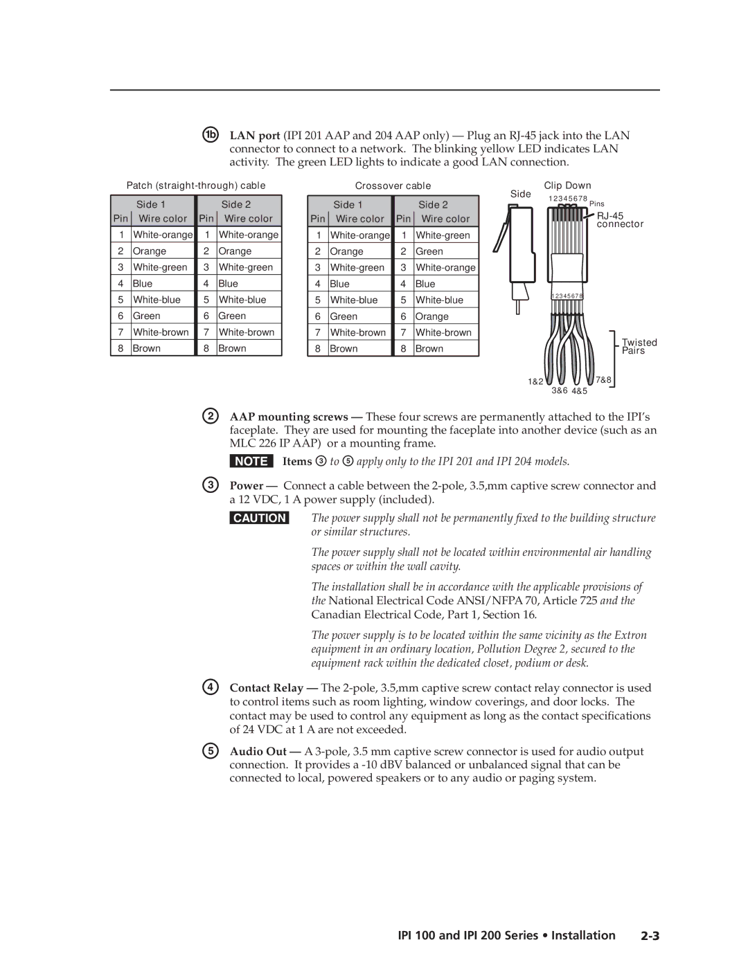
ÅLAN port (IPI 201 AAP and 204 AAP only) — Plug an
Patch |
| Crossover cable | Side | Clip Down | ||||||
| Side 1 |
|
| Side 2 |
| Side 1 |
| Side 2 | 1 2 3 4 5 6 7 8 Pins | |
|
|
|
|
|
| |||||
Pin | Wire color | Pin |
| Wire color | Pin | Wire color | Pin | Wire color |
| |
1 | 1 |
|
|
|
|
| connector | |||
1 | 1 |
|
| |||||||
2 | Orange | 2 | Orange | 2 | Orange | 2 | Green |
|
| |
3 | 3 | 3 | 3 |
|
| |||||
4 | Blue | 4 | Blue | 4 | Blue | 4 | Blue |
|
| |
5 | 5 | 5 | 5 |
| 1 2 3 4 5 6 7 8 | |||||
|
| |||||||||
6 | Green | 6 | Green | 6 | Green | 6 | Orange |
|
| |
7 | 7 | 7 | 7 |
| Twisted | |||||
8 | Brown | 8 | Brown | 8 | Brown | 8 | Brown |
| ||
| Pairs | |||||||||
|
|
|
|
|
|
|
|
| 1&2 | 7&8 |
|
|
|
|
|
|
|
|
|
| 3&6 4&5 |
|
| B | AAP mounting screws — These four screws are permanently attached to the IPI’s | |||||||
|
|
|
| faceplate. They are used for mounting the faceplate into another device (such as an | ||||||
MLC 226 IP AAP) or a mounting frame.
| N Items C to E apply only to the IPI 201 and IPI 204 models. |
C | Power — Connect a cable between the |
| a 12 VDC, 1 A power supply (included). |
| C The power supply shall not be permanently fixed to the building structure |
| or similar structures. |
| The power supply shall not be located within environmental air handling |
| spaces or within the wall cavity. |
| The installation shall be in accordance with the applicable provisions of |
| the National Electrical Code ANSI/NFPA 70, Article 725 and the |
| Canadian Electrical Code, Part 1, Section 16. |
| The power supply is to be located within the same vicinity as the Extron |
| equipment in an ordinary location, Pollution Degree 2, secured to the |
| equipment rack within the dedicated closet, podium or desk. |
D | Contact Relay — The |
| to control items such as room lighting, window coverings, and door locks. The |
| contact may be used to control any equipment as long as the contact specifications |
| of 24 VDC at 1 A are not exceeded. |
E | Audio Out — A |
| connection. It provides a |
| connected to local, powered speakers or to any audio or paging system. |
IPI 100 and IPI 200 Series • Installation |