DishDrawer
Service Manual
NZ AU GB IE US CA
DD607 & DD247
Brand
FEATURED PRODUCT & CONTACT ADDRESSES
Standard Double Models
Description
DD24SCW7
Standard Single Models
Single, Designer, Brushed Stainless
Tall Tub Double Models
DD24SDFTX7
Tall Tub Single Models
Single, Tall Tub, Classic White
Single, Tall Tub, Classic, Stainless Steel
CONTENTS
WIRING DIAGRAMS
SERVICE PROCEDURES
10 NOTES
1.1.1 Electrical Safety
1 SERVICE REQUIREMENTS
1.1.9 Diagnostics
1.1.2 Electrostatic Discharge
1.2.1 Static Strap
1.2 Specialised Tools
2 DIMENSIONS & SPECIFICATIONS
22 15/16 ”
22 15/16”
Specification
Component Specifications
8.0 Ohms per winding, 16 ohms phase to
Component
Hall sensor
Wash
Wash Cycle
Post
Time
DD60 United States/Canada Wash Profiles
DD60 Australia/New Zealand Wash Profiles
Wash Cycle
Wash
3.3.1 Tub Home Sensor
3 TECHNICAL OVERVIEW
3.3.2 Touch Switches
3.3.3 Wireless Remote some integrated models only
3.3.4 Operation some integrated models only
Air Valve
3.3.5 Wireless Receiver
Sluicing Jets
3.4.1 Rotor
3.4.4 Drain Filter
3.4.3 Filter Plate
3.5.1 When Activated
3.5.2 During a Power Failure
3.7.1 Water Inlet
3.7.3 Amount of Water
3.7.2 Dispensing Detergent and Rinse Aid
Flood Sensor
3.7.4 Flood Protection
3.8.2 Heating the Water
3.8.1 The Heating Element
3.8.3 Maintaining the Temperature
3.8.4 Over Heat Protection
Non Return Valve
3.11.1 The Filter System
3.11.2 Removing and Cleaning the Drain Filter and Filter Plate
3.12.1 Integrated Single Drawer Venting some models only
Strainer Spigot Strainer
Not Wireless Model
4 OPTION ADJUSTMENT MODE
4.1.2 Rinse Aid Setup rA
Setup
4.1.3 Water Supply Hardness Setup hd
DishDrawer Setting
Grains per Gallon
Parts per Million
4.2.2 Designer Models
4.2.1 Classic Models
4.2.4 Integrated with Wireless Remote Control
4.2.3 Integrated Models
button, which will increase or decrease the amount of LED’s on the
Option
Closed Drawer autolock using the remote control
Rinse aid
Water softener
5 DIAGNOSTICS
5.1.1 Display Mode
5.1.2 Hardware Output Mode HO
Rinse Aid Pump operates as a valve for diagnostic purposes only
5.1.4 Continuous Cycle Mode CC
5.1.3 Fast Cycle FC
5.1.5 Temperature and Voltage Display
5.1.6 Show Off/ Showroom Wash Mode
Playing Tunes
Program Indicators
5.2.1 Diagnostic Mode
Program Button
5.2.2 Display Mode
5.2.5 Continous Cycle Mode CC
5.2.4 Fast Cycle Mode FC
6 FAULT CODES AND POOR PERFORMANCE
Fault
Fault Code
LED Display
Possible Causes
6.1.1 Sub Code Faults
Fast & Eco LED’s
Fast, Delicate
QUESTION
Poor Dry Performance Non Vented
Is the customer complaining of
plastic items not drying?
problem
How to resolve the
Customers Complaint - food particles left on dishes
Customers Complaint - coffee/tea stains left in cups
More on next page
white chalky film on them
How to resolve the problem
7.1 Fault Code Problem Solving
7 FAULT FINDING PROCEDURE
DO NOT REPLACE COMPONENTS ON A TUB WITH THIS WARNING
Wet E1- Water in the Chassis Base
Dry E1 - No Water in the Chassis Base
Prefinished models
Controller Harness P201 Corrosion Damage Example
Fault code E2 - Sub Code 03 - Motor Not Drawing Enough Current
NOTE For more detailed component testing, refer to page
Fault Code E5 - Sub Code 01 - Not Starting
Fault Code E5 - Lid Fault
Fault Code E5 - Sub Code 02 - No Current
Fault Code E5 - Sub Code 04 - Not Stalling
Flap
Fan Housing Locking Tabs
Fault Code E7 - Sub Code 02 - Under Current
Fault Code E7 - Detergent Diverter Valve
Fault Code E7 - Sub Code 03 - Over Current
Detergent Diverter Coil Harness Pin Pin
Water softener brine pump
There are 4 sub codes which relate to this fault code
If the problem persists replace the bottom controller
8 WIRING DIAGRAMS
8.2 Power Distribution Concept
Lower Tub Shown Only
8.3 Wiring Diagram
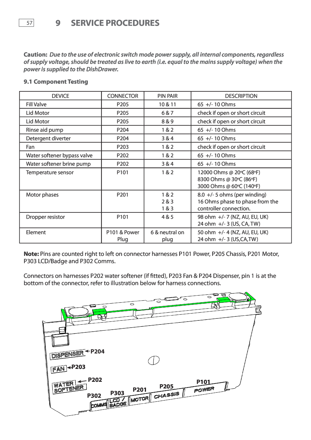
P204
9 SERVICE PROCEDURES
P203
P202
1. Open the drawer
Retaining Screw
Clip Cowling
Rail Clip
1. Open the drawer and remove the drawer front refer section
1. Remove the drawer front refert section
1. Remove the cutlery basket and rack from the tub
1. Remove the drawer front refer Section
Earth Wire Element Cover
Clips Clips
Drain Hose Fill Hose
1. Remove the wiring cover refer section
1. Remove the tub as per section
Trim Channel
Trim
Hex Drive Screws Rail Rear Locating Tabs
Water Valve
Clips Inlet Hose Flood Sensor MFB
Fill Hoses Water Inlet Hose Chassis Clip
Wiring Harness Link Clip 15mm 3/4”
Trim Clips
9.28 Single Integrated Vent Duct Removal Some models only
T10 Torx Screw
Slide Off Tub
1. Remove the tub to gain access to the duct, refer section
1. Remove the door panel, refer section
Pairing Procedure
Receiver Replacement Procedure
To Pair Remote to Receiver
Transmit LED indicator Top Tub start button on doubles
10 NOTES
11.2011
NZ AU GB IE US CA F&P PN 590409 A