The port
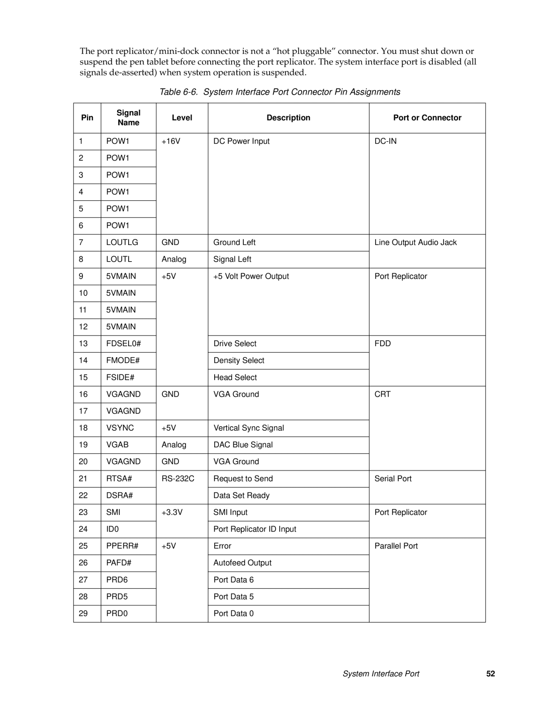
Table 6-6. System Interface Port Connector Pin Assignments
Pin | Signal | Level | Description | Port or Connector | ||
Name | ||||||
|
|
|
|
| ||
|
|
|
|
|
| |
1 | POW1 | +16V | DC Power Input | |||
|
|
|
|
|
| |
2 | POW1 |
|
|
|
| |
|
|
|
|
|
| |
3 | POW1 |
|
|
|
| |
|
|
|
|
|
| |
4 | POW1 |
|
|
|
| |
|
|
|
|
|
| |
5 | POW1 |
|
|
|
| |
|
|
|
|
|
| |
6 | POW1 |
|
|
|
| |
|
|
|
|
|
| |
7 | LOUTLG | GND | Ground Left | Line Output Audio Jack | ||
|
|
|
|
|
| |
8 | LOUTL | Analog | Signal Left |
| ||
|
|
|
|
|
| |
9 | 5VMAIN | +5V | +5 Volt Power Output | Port Replicator | ||
|
|
|
|
|
| |
10 | 5VMAIN |
|
|
|
| |
|
|
|
|
|
| |
11 | 5VMAIN |
|
|
|
| |
|
|
|
|
|
| |
12 | 5VMAIN |
|
|
|
| |
|
|
|
|
|
| |
13 | FDSEL0# |
|
| Drive Select | FDD | |
|
|
|
|
|
| |
14 | FMODE# |
|
| Density Select |
| |
|
|
|
|
|
| |
15 | FSIDE# |
|
| Head Select |
| |
|
|
|
|
| ||
16 | VGAGND | GND | VGA Ground | CRT | ||
|
|
|
|
|
| |
17 | VGAGND |
|
|
|
| |
|
|
|
|
| ||
18 | VSYNC | +5V | Vertical Sync Signal |
| ||
|
|
|
|
| ||
19 | VGAB | Analog | DAC Blue Signal |
| ||
|
|
|
|
| ||
20 | VGAGND | GND | VGA Ground |
| ||
|
|
|
|
| ||
21 | RTSA# | Request to Send | Serial Port | |||
|
|
|
|
|
| |
22 | DSRA# |
|
| Data Set Ready |
| |
|
|
|
|
| ||
23 | SMI | +3.3V | SMI Input | Port Replicator | ||
|
|
|
|
|
| |
24 | ID0 |
|
| Port Replicator ID Input |
| |
|
|
|
|
| ||
25 | PPERR# | +5V | Error | Parallel Port | ||
|
|
|
|
|
| |
26 | PAFD# |
|
| Autofeed Output |
| |
|
|
|
|
|
| |
27 | PRD6 |
|
| Port Data 6 |
| |
|
|
|
|
|
| |
28 | PRD5 |
|
| Port Data 5 |
| |
|
|
|
|
|
| |
29 | PRD0 |
|
| Port Data 0 |
| |
|
|
|
|
|
| |
System Interface Port | 52 |