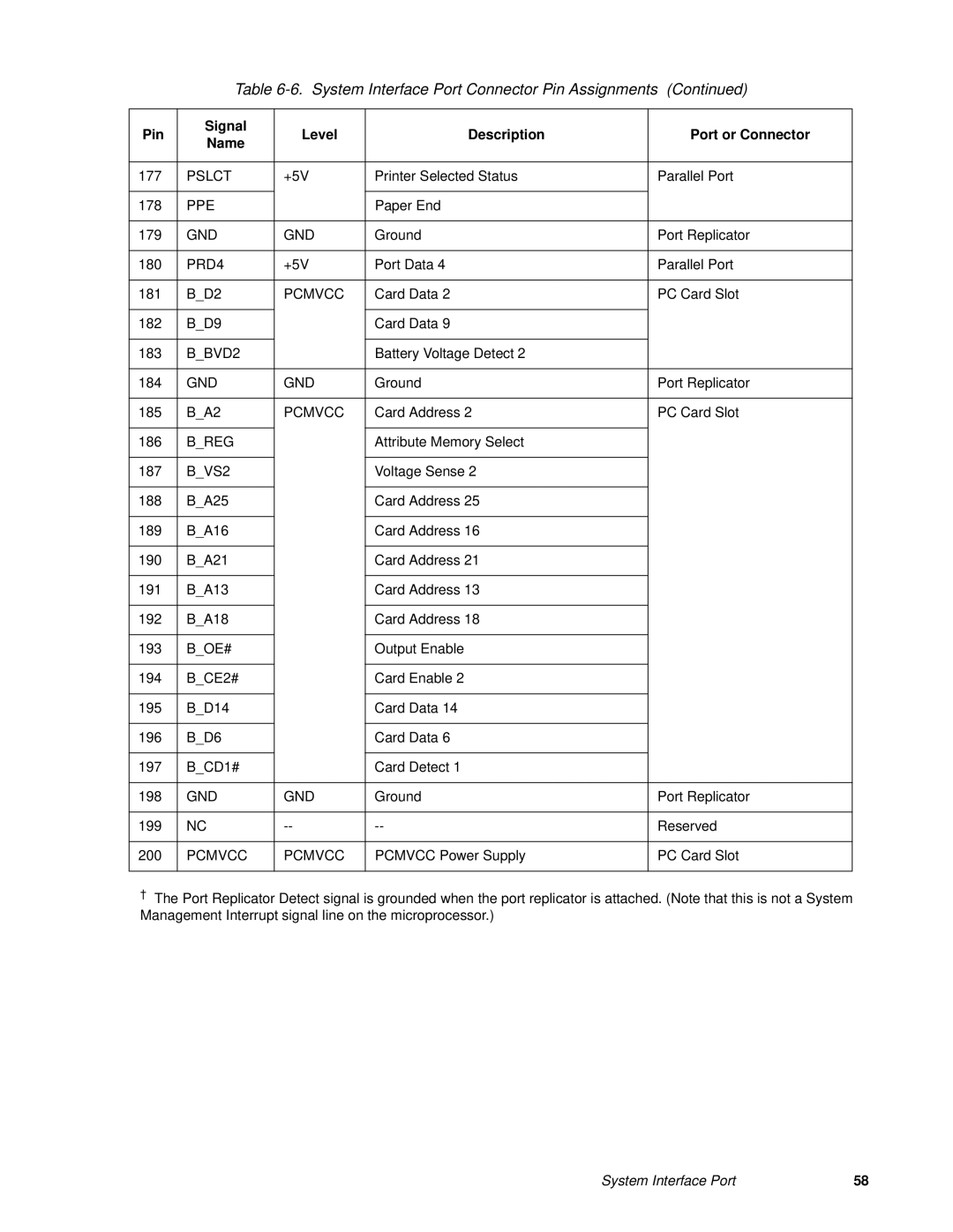
| Table | (Continued) | ||||
|
|
|
|
|
|
|
Pin | Signal | Level | Description |
| Port or Connector | |
Name |
| |||||
|
|
|
|
|
| |
|
|
|
|
|
|
|
177 | PSLCT | +5V | Printer Selected Status |
| Parallel Port | |
|
|
|
|
|
|
|
178 | PPE |
|
| Paper End |
|
|
|
|
|
|
|
| |
179 | GND | GND | Ground |
| Port Replicator | |
|
|
|
|
|
| |
180 | PRD4 | +5V | Port Data 4 |
| Parallel Port | |
|
|
|
|
|
| |
181 | B_D2 | PCMVCC | Card Data 2 |
| PC Card Slot | |
|
|
|
|
|
|
|
182 | B_D9 |
|
| Card Data 9 |
|
|
|
|
|
|
|
|
|
183 | B_BVD2 |
|
| Battery Voltage Detect 2 |
|
|
|
|
|
|
|
| |
184 | GND | GND | Ground |
| Port Replicator | |
|
|
|
|
|
| |
185 | B_A2 | PCMVCC | Card Address 2 |
| PC Card Slot | |
|
|
|
|
|
|
|
186 | B_REG |
|
| Attribute Memory Select |
|
|
|
|
|
|
|
|
|
187 | B_VS2 |
|
| Voltage Sense 2 |
|
|
|
|
|
|
|
|
|
188 | B_A25 |
|
| Card Address 25 |
|
|
|
|
|
|
|
|
|
189 | B_A16 |
|
| Card Address 16 |
|
|
|
|
|
|
|
|
|
190 | B_A21 |
|
| Card Address 21 |
|
|
|
|
|
|
|
|
|
191 | B_A13 |
|
| Card Address 13 |
|
|
|
|
|
|
|
|
|
192 | B_A18 |
|
| Card Address 18 |
|
|
|
|
|
|
|
|
|
193 | B_OE# |
|
| Output Enable |
|
|
|
|
|
|
|
|
|
194 | B_CE2# |
|
| Card Enable 2 |
|
|
|
|
|
|
|
|
|
195 | B_D14 |
|
| Card Data 14 |
|
|
|
|
|
|
|
|
|
196 | B_D6 |
|
| Card Data 6 |
|
|
|
|
|
|
|
|
|
197 | B_CD1# |
|
| Card Detect 1 |
|
|
|
|
|
|
|
| |
198 | GND | GND | Ground |
| Port Replicator | |
|
|
|
|
|
|
|
199 | NC |
|
| Reserved | ||
|
|
|
|
|
| |
200 | PCMVCC | PCMVCC | PCMVCC Power Supply |
| PC Card Slot | |
|
|
|
|
|
|
|
†The Port Replicator Detect signal is grounded when the port replicator is attached. (Note that this is not a System Management Interrupt signal line on the microprocessor.)
System Interface Port | 58 |
