4.6 Read/write Circuit
4.6 Read/write Circuit
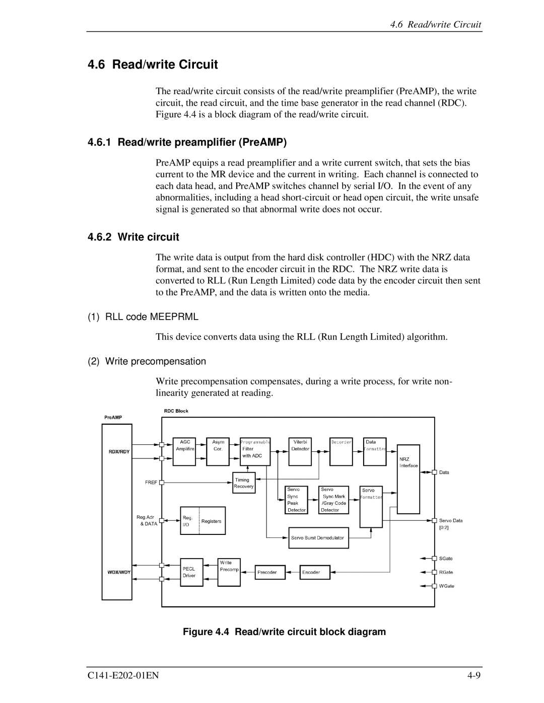
The read/write circuit consists of the read/write preamplifier (PreAMP), the write circuit, the read circuit, and the time base generator in the read channel (RDC). Figure 4.4 is a block diagram of the read/write circuit.
4.6.1 Read/write preamplifier (PreAMP)
PreAMP equips a read preamplifier and a write current switch, that sets the bias current to the MR device and the current in writing. Each channel is connected to each data head, and PreAMP switches channel by serial I/O. In the event of any abnormalities, including a head
4.6.2 Write circuit
The write data is output from the hard disk controller (HDC) with the NRZ data format, and sent to the encoder circuit in the RDC. The NRZ write data is converted to RLL (Run Length Limited) code data by the encoder circuit then sent to the PreAMP, and the data is written onto the media.
(1) RLL code MEEPRML
This device converts data using the RLL (Run Length Limited) algorithm.
(2) Write precompensation
Write precompensation compensates, during a write process, for write non- linearity generated at reading.