4.7 Servo Control
4.7.3 Servo frame format
As the servo information, the IDD uses the
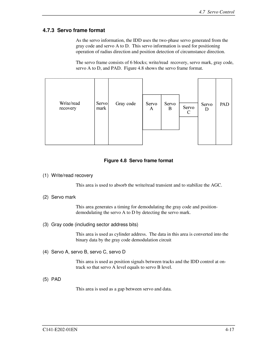
The servo frame consists of 6 blocks; write/read recovery, servo mark, gray code, servo A to D, and PAD. Figure 4.8 shows the servo frame format.
Figure 4.8 Servo frame format
(1) Write/read recovery
This area is used to absorb the write/read transient and to stabilize the AGC.
(2) Servo mark
This area generates a timing for demodulating the gray code and position- demodulating the servo A to D by detecting the servo mark.
(3) Gray code (including sector address bits)
This area is used as cylinder address. The data in this area is converted into the binary data by the gray code demodulation circuit
(4) Servo A, servo B, servo C, servo D
This area is used as position signals between tracks and the IDD control at on- track so that servo A level equals to servo B level.
(5) PAD
This area is used as a gap between servo and data.