4.2.2Head
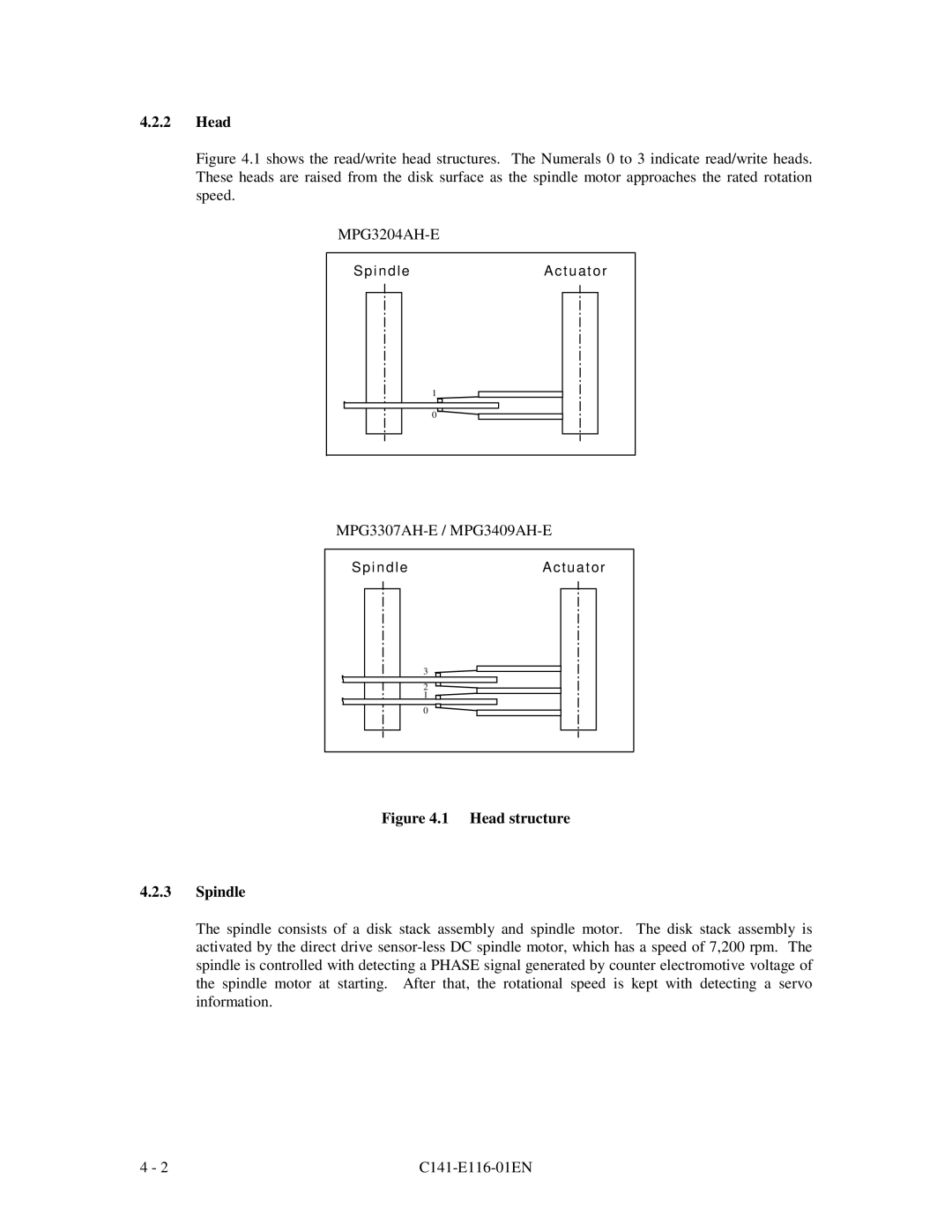
Figure 4.1 shows the read/write head structures. The Numerals 0 to 3 indicate read/write heads. These heads are raised from the disk surface as the spindle motor approaches the rated rotation speed.
MPG3204AH-E
SpindleActuator
1 |
0 |
Spindle | Actuator |
| 3 |
| 2 |
| 1 |
| 0 |
Figure 4.1 Head structure
4.2.3Spindle
The spindle consists of a disk stack assembly and spindle motor. The disk stack assembly is activated by the direct drive
4 - 2 |
|