3.4.4Power supply connector (CN1)
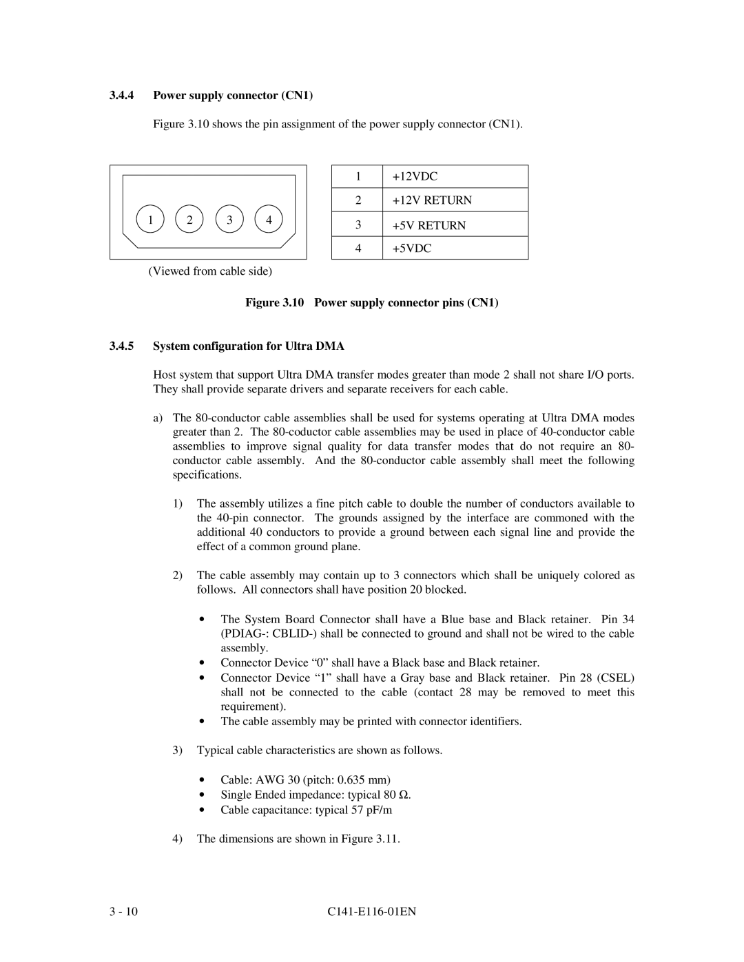
Figure 3.10 shows the pin assignment of the power supply connector (CN1).
1 | 2 | 3 | 4 |
(Viewed from cable side)
1+12VDC
2+12V RETURN
3+5V RETURN
4+5VDC
Figure 3.10 Power supply connector pins (CN1)
3.4.5System configuration for Ultra DMA
Host system that support Ultra DMA transfer modes greater than mode 2 shall not share I/O ports. They shall provide separate drivers and separate receivers for each cable.
a)The
1)The assembly utilizes a fine pitch cable to double the number of conductors available to the
2)The cable assembly may contain up to 3 connectors which shall be uniquely colored as follows. All connectors shall have position 20 blocked.
•The System Board Connector shall have a Blue base and Black retainer. Pin 34
•Connector Device “0” shall have a Black base and Black retainer.
•Connector Device “1” shall have a Gray base and Black retainer. Pin 28 (CSEL) shall not be connected to the cable (contact 28 may be removed to meet this requirement).
•The cable assembly may be printed with connector identifiers.
3)Typical cable characteristics are shown as follows.
•Cable: AWG 30 (pitch: 0.635 mm)
•Single Ended impedance: typical 80 Ω .
•Cable capacitance: typical 57 pF/m
4)The dimensions are shown in Figure 3.11.
3 - 10 |
|