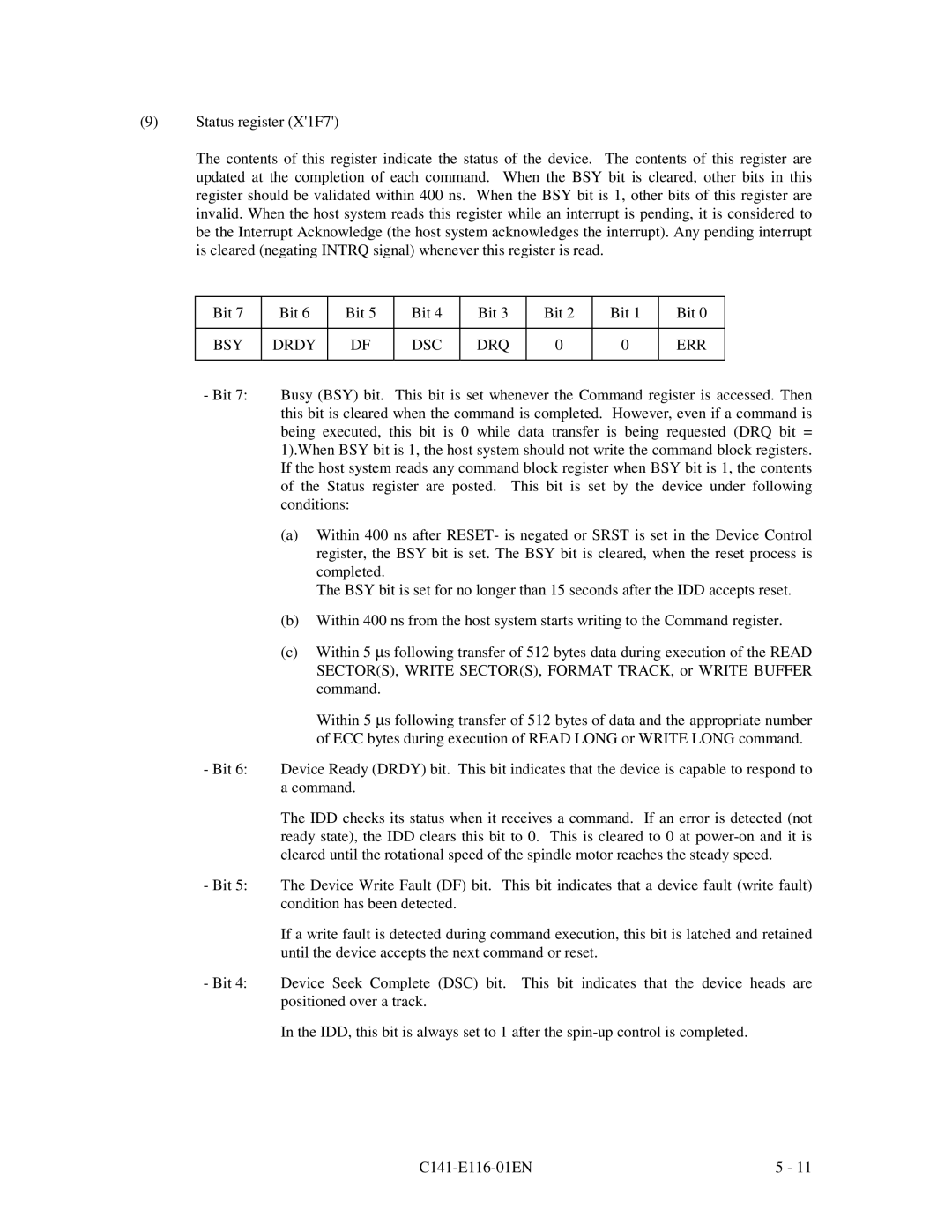
(9) | Status register (X'1F7') |
|
|
|
|
|
|
|
| |||
| The contents of this register indicate the status of the device. The contents of this register are | |||||||||||
| updated at the completion of each command. When the BSY bit is cleared, other bits in this | |||||||||||
| register should be validated within 400 ns. When the BSY bit is 1, other bits of this register are | |||||||||||
| invalid. When the host system reads this register while an interrupt is pending, it is considered to | |||||||||||
| be the Interrupt Acknowledge (the host system acknowledges the interrupt). Any pending interrupt | |||||||||||
| is cleared (negating INTRQ signal) whenever this register is read. |
|
|
| ||||||||
|
|
|
|
|
|
|
|
|
|
|
|
|
| Bit 7 | Bit 6 |
| Bit 5 |
| Bit 4 | Bit 3 | Bit 2 |
| Bit 1 | Bit 0 |
|
|
|
|
|
|
|
|
|
|
|
|
|
|
| BSY | DRDY |
| DF |
| DSC | DRQ | 0 |
| 0 | ERR |
|
|
|
|
|
|
|
|
|
|
|
| ||
| - Bit 7: | Busy (BSY) bit. |
| This bit is set whenever the Command register is accessed. Then | ||||||||
|
| this bit is cleared when the command is completed. However, even if a command is | ||||||||||
|
| being | executed, | this bit is 0 while data transfer | is being requested (DRQ bit = | |||||||
|
| 1).When BSY bit is 1, the host system should not write the command block registers. | ||||||||||
|
| If the host system reads any command block register when BSY bit is 1, the contents | ||||||||||
|
| of the Status register are posted. This bit is set by the device under following | ||||||||||
|
| conditions: |
|
|
|
|
|
|
|
| ||
|
| (a) Within 400 ns after RESET- is negated or SRST is set in the Device Control | ||||||||||
|
|
| register, the BSY bit is set. The BSY bit is cleared, when the reset process is | |||||||||
|
|
| completed. |
|
|
|
|
|
|
|
| |
|
|
| The BSY bit is set for no longer than 15 seconds after the IDD accepts reset. | |||||||||
|
| (b) Within 400 ns from the host system starts writing to the Command register. | ||||||||||
|
| (c) Within 5 ∝ s following transfer of 512 bytes data during execution of the READ | ||||||||||
|
|
| SECTOR(S), WRITE SECTOR(S), FORMAT TRACK, or WRITE BUFFER | |||||||||
|
|
| command. |
|
|
|
|
|
|
|
| |
|
|
| Within 5 ∝ s following transfer of 512 bytes of data and the appropriate number | |||||||||
|
|
| of ECC bytes during execution of READ LONG or WRITE LONG command. | |||||||||
| - Bit 6: | Device Ready (DRDY) bit. This bit indicates that the device is capable to respond to | ||||||||||
|
| a command. |
|
|
|
|
|
|
|
| ||
The IDD checks its status when it receives a command. If an error is detected (not ready state), the IDD clears this bit to 0. This is cleared to 0 at
-Bit 5: The Device Write Fault (DF) bit. This bit indicates that a device fault (write fault) condition has been detected.
If a write fault is detected during command execution, this bit is latched and retained until the device accepts the next command or reset.
-Bit 4: Device Seek Complete (DSC) bit. This bit indicates that the device heads are positioned over a track.
In the IDD, this bit is always set to 1 after the
| 5 - 11 |
