Model FS-5070
00016050112
Important Notice
Safety Instructions
Iii
For IC-302 option operation
Distress Alert Message Procedure
Distress Cancellation Proc. Select frequency Push Enter
Canceling Distress Alert
Communicate, via radiotelephone, with the coast station
Send cancel msg. by voice on 2182.0 kHz
Table of Contents
Send calls
Viii
Menu Operation
Nbdp TRANSMITTING, Receiving
11-2
11.1
11-1
11.2
General
Features
Foreword
Xii
Xiii
Program Number
FS-1570
System Configurations
Standard configuration is shown with solid line
Xiv
Terminal Unit
FS-2570
FS-5070
Xvi
Description of controls
PWR/VOL knob Turns the power on/off Adjusts volume
Operational Overview
Controls
Turning the Power On/Off
Radiotelephone RT Screen
Radiotelephone RT screen
DSC Standby Screen
Indication
DSC standby screen
Setting Scan Frequencies
Control Unit Dimmer, Contrast
Loudspeaker
Controls become inoperative
Setting for Auto Acknowledgement
System Characteristics
Equipment priority
Intercom
Automatic setting of working frequency
Choosing Class of Emission
SSB Radiotelephone
Rotate the Enter knob to set band or channel desired
Choosing Channel, Frequency
Choosing channel
Choosing band and band channel with the Enter knob
Entering frequency with the numeric keys
Transmitting procedure
Transmitting
Choosing frequency
Condition of the transmitting unit
Reducing transmitter power
Receiving
RF gain sensitivity adjustment
Checking the transmitting power
Rotate the Enter to adjust and then push the Enter knob
Squelch on/off
Receiving AM broadcasting stations
Squelch function
Noise blanker
High Tension Hazard
When Automatic Tuning Fails
User Channels
Call Description
What is DSC?
DSC Overview
DSC Message
Contents of a DSC call
Alarm Frequency interval
Audio Alarms
Interpreting Call Displays
Receive calls
Distress receive call
View message
Send calls
Individual receive call
Received message
Compose msg
Individual send call
Ship in Distress
Distress Operations
Sending Distress Alert
Distress operation overview
Distress Operations
Received message
Push the Enter knob to open the Input Type menu
Twice and then go to step
Push the Enter knob to open the latitude input window
Compose msg
Push the Enter knob to open the time input window
Communicating by Nbdp Terminal Unit
Display changes as below example
Distress alert received on MF band
Receiving a Distress Alert
Action for ship receiving distress alert on MF band
Distress alert message received
Distress acknowledge message in progress
Distress alert received on HF band
Agree
Action for ships receiving distress alert on HF band
Sending the distress relay to coast station on HF band
Wait for distress relay acknowledge
Push the Enter knob to open the DSC FREQ. Menu
Sending distress relay to coast station
Sending Distress Relay on Behalf of a Ship in Distress
Ship ID in Dist
Push the Enter knob to open the Ship ID in Dist window
Telephone
Distress relay ack message received
Press the Cancel key to silence the audio alarm
Priority distress Transmit sure?
Distress relay coast message in progress
Area Circle
Sending distress relay to area ships
Ship ID in Dist Nature Telephone
Distress relay area message in progress
Receiving Distress Relay from Coast Station
Cancelling Distress Call
Distress Cancellation Proc. Select frequency Push Enter
Operation overview
Routine Message CALLING, Receiving
Individual Call
Sending an individual call
NBDP-ARQ
Push the Enter knob to open the Priority menu
How to Set Working Frequency, Channel
Safety or urgency priority
Routine priority
Compose msg
How to Set DSC Frequency
Able acknowledge message received
Press Call key for forced transmission
Unable acknowledge call received
Able acknowledge call received
Sending automatic acknowledge ACK BQ with comply type Able
Receiving an individual call
No response! Try calling again?
Send Able acknowledge Send Unable acknowledge Manually
Unable acknowledge message in progress
Sending automatic acknowledge ACK BQ with comply type Unable
Manually acknowledging individual call with Able
Manually acknowledging individual call with Unable
No Reason Reason Busy
Group Call
Sending a group call
Press the 2/DSC key Select Message
MHZ
Sending message by Nbdp Terminal Unit
Receiving a group call
Receiving message by Nbdp Terminal Unit
Geographical Area Call
Area
Sending a geographical area call
Receiving a geographical area call
Geographical Area Sender ID
Sending a neutral craft call
Neutral Craft Call
Receiving a neutral craft call
Sending a medical transport call
Medical Transport Call
2187.5
Receiving a medical transport call
Press the Cancel key to return to the radiotelephone screen
Receiving a Polling Request
Automatic reply
Manual reply
Sending own ship’s position to other station
Position Call
Requesting other ship’s position
Finding position of other station
Station ID
Automatic reply
Cancel call Press the Cancel key
Position call other ship requests your position
Acknowledge message received
Manual reply
If canceling to send the reply, press the Cancel key
Sending a Pstn call, receiving acknowledge back ACK BQ
Pstn Call
To scroll
Push the Enter knob to open the TEL NO. menu
Waiting for acknowledgement
Receiving a Pstn call, sending acknowledge back ACK BQ
Then, one of the following displays appears
Unable acknowledge message received
Shortly thereafter, one of the following messages appears
No response! charge information
Manual
To view the contents of a file, do the following
To return to the log selected, press the Cancel key
Deleting log files
This page is intentionally left blank
Adjusting Handset Volume
Setup
Menu Operation
User ch entry
Noise Blanker
Squelch Frequency
Registering user channels
Push the Enter knob to open the user channel options window
Deleting individual user channels
Preparing TX Message
Deleting user channels
Preparing individual calls
Frequency
Push the Enter knob to open the Station ID entry window
Push the Enter knob to open the file name entry window
How to Enter File Name and Number
Push the Enter knob to continue
Preparing group calls
Message 2 MHZ
Preparing Pstn calls
Preparing test call
Editing before sending
Sending prepared messages
Deleting send message
Sending without modification
Manual Entry of Position and Time
Printing List of Send Message Files
Deleting all messages
After last digit
Memory clear
Date and Time Setting
Date/Time setup
Memory Clear
Clearing received ordinary log
Clearing received distress log
Clearing transmitted log
Setting Alarms
Restoring to default setting
Clearing user channels
Sound setup
Sound Setting
OFF Hook
Setting the Auto ACK Details
Sample printouts
Printing Messages
Distress and safety frequencies
Routine frequencies
Scan freq setup
Key assign setup
Key Assignment
Special Messages
FAX Enable/Disable
Speaker Setting in Off Hook
Operation Timer Off
This page is intentionally left blank
Nbdp System Overview
Turning on the Nbdp System
Nbdp terminal unit, printer and keyboard
Communication status display
Features of the IB-583
Description of Equipment
Terminal unit
Keyboard
Keyboard
Underline
Function Keys, Menu Operation
Menu conventions
Inverse video
Selecting menu items and options
Menu overview
Selecting menus
File menu
Function key description
Copy
Function key F2 Edit menu
Undo
Cut
Call Station
Cancel Sending
Timer Operation
Function key F3 Operate menu
Displays desired calendar month and year. To change year
Or month, choose item with ↑ or ↓ key and change setting
Function key F4 Window menu
Window menu
Scan Entry
Timer Operation Entry
Function key F5 Station menu
Station Entry
TX/RX MSG Save
Setup
Slave Delay
Function key F6 System menu
Function key F10 Break Disconnects the line
Cursor is choosing Window Color Setup press the Enter key
Answerback code entry screen
Nbdp Preparations
Registering Answerback Code & ID Codes
Registering answerback code
ID code entry screen
Registering ID codes
Message for confirmation of code entered
If the code is correct, press the Enter key again
Registering stations
Station List
OK/Cancel prompt
Editing/Deleting stations
Scanning group list
3 5 0
Timer Programming
Registering timer programs
Timer operation entry screen
User channel entry screen
Editing/Deleting timer programs
Scan entry screen
Scan Channel Groups
Editing/Deleting user channels
Registering scan channel groups
Press the Enter key twice Press the ESC key
Editing/Deleting scan channel groups
How a file is opened
Nbdp File Operations
Opening and Closing Files
Creating Files
Formatting floppy disks
Saving a File
Close text screen
Editing Files
Saving a file
Cutting and pasting text
Pasting text
Copying and pasting text
Cutting text
Highlight
Search screen
Copy and paste flow diagram
Select all
Searching text
Replace screen
Replacing text
Goto line
Goto top, Goto bottom
Opening a file
Switching between files
Opening Files
Renaming Files
Printing Files
Saving a File Under a New Name
Deleting Files
Real Time Printing
Set frequency screen
Nbdp TRANSMITTING, Receiving
Manual Calling
10-1
Manual calling screen
10-2
Press the 1 key to choose Call Station
ARQ Mode Operation
10-3
Establishing connection
Send file screen
10-4
Transmit message by one of the following methods
Sending a file stored on a floppy disk
Stopping transmission
FEC Mode Operation
Choosing Receive Mode
10-5
Communication Example
10-6
Communications example
Table of abbreviations
10-7
Timer operation list
Timer Operation
Enabling timer operation
Command and abbreviation
Stopping timer operation
Scanning
10-9
10-10
Communication Buffer
Preparing Macrofiles for Automatic Telex
Automatic telex overview
Registering scan groups
Preparations
10-11
Registering answerback code
Command Function
Commands
Command Parameter Content
Commands processed by Danish coast station Lyngby
Actual procedure for store-and-forward telex
Store-and-forward method
10-13
10-14
Sample macrofile for store-and-forward method
Close text prompt
Sample Dirltx macrofile
Dirtlx macrofile
10-15
Sample Dirtlx macrofile
10-16
Procedure for Dirtlx
10-17
Automatic Telex using Macrofile
Basic procedure
Actual procedure
10-18
Call macro screen
Press the ↓ key to choose a macrofile Press the Enter key
Maintenance & Troubleshooting
Radiotelephone Test
11-1
11-2
Maintenance
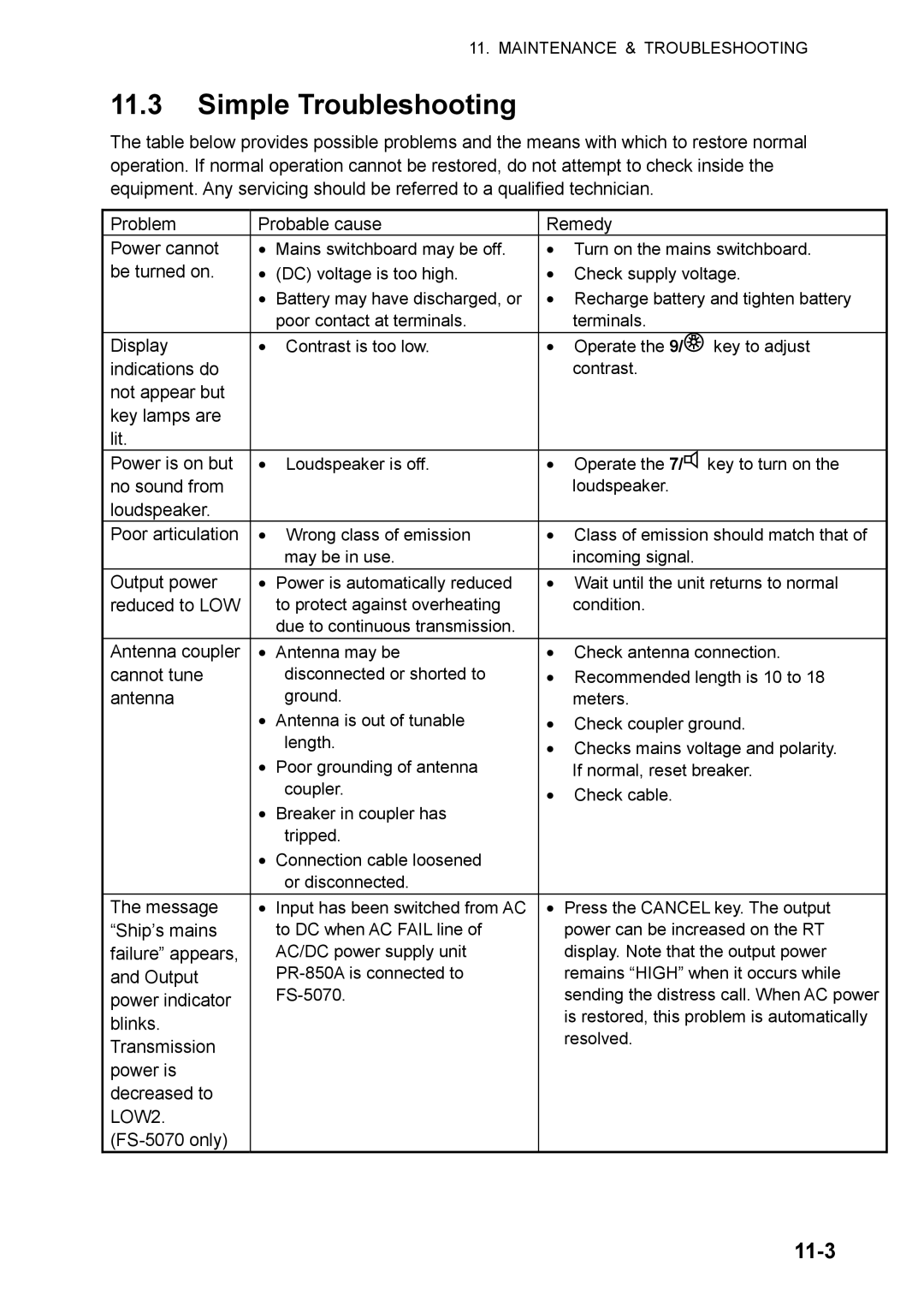
Simple Troubleshooting
11-3
FS-5070 only
Error Messages
Error messages
11-4
11-5
Replacement of Fuses
11-6
Test Call
11-7
Do the either way depending on the message shown in step
Test acknowledge message received
Nbdp Terminal Unit Maintenance
Tone test
11-9
System menu Example IB-583
Self test results
11-10
Tone test 2 Fox
Tone test 3 Beta
Appendix
Menu Tree
AP-1
AP-2
Nbdp terminal unit telex
14. = Ship-to-ship
Frequency Tables
AP-3
TX kHz RX kHz Remarks File Name
AP-4
Custom channels to be programmed by Furuno dealers
AP-5
MF band working carrier frequencies ref. US CFR 47 Part
AP-6
MF band SSB working carrier frequencies
AP-7
MHz ITU SSB carrier frequencies ITU RR Appendix
AP-8
AP-9
12/16 ITU SSB carrier frequencies ITU RR Appendix
AP-10
18/19, 22, 25/26 ITU SSB carrier frequencies ITU RR Appendix
AP-11
MF band telex frequency table
Frequency /4
AP-12
ITU Telex frequency /4
AP-13
AP-14
ITU Telex Frequency /4
AP-16
Telex Abbreviations
Input sentences IEC
Digital Interface IEC
Sentences
AP-17
AP-18
GLL Geographic position latitude/longitude
ZDA Time and date
GNS Gnss fix data
AP-19
RMC Recommended minimum specific GPS/TRANSIT data
AP-20
AP-21
Schematic diagram
Parts List
AP-22
Transceiver unit FS-1570T
Transceiver unit FS-2570T
AP-23
Control unit FS-2571C
AP-24
Control unit FS-5070T
AP-25
Parts Location
FS-1570T
AP-26
AP-27
Transceiver unit FS-2570T
AP-28
Transceiver unit FS-5070T
Comb
AP-29
AP-30
Control unit FS-2571C
FS-1570/2570/5070
Specifications of SSB Radiotelephone
DSC/WATCH Keeping Receiver
DSC/WATCH Receiver FS-5070
Terminal Unit IB-581 FS-1570/2570
Nbdp Function Option
Antenna Coupler FS-5070
Antenna Coupler FS-1570/2570
Coating Color
Distress relay
Index
IN-2
0560
Publication No. DOC-1028
0560