2.2Location of Connectors
MONITOR UNIT 10S2076 (5/10 m) |
|
| |
|
|
| |
|
| 10S2076 (5/10 m) | |
CONTROL UNIT |
| ||
10S2074 (10 m) or 10S2075 (30 m) | CONTROL UNIT | ||
|
|
| |
Transceiver |
|
| Monitor |
|
| (Local supply) | |
unit |
|
| |
Monitor unit |
|
|
|
Control unit |
|
| Monitor cable |
|
|
| |
Monitor unit |
|
| (Local supply) |
|
|
| |
Control unit |
|
|
|
External |
|
|
|
monitor |
|
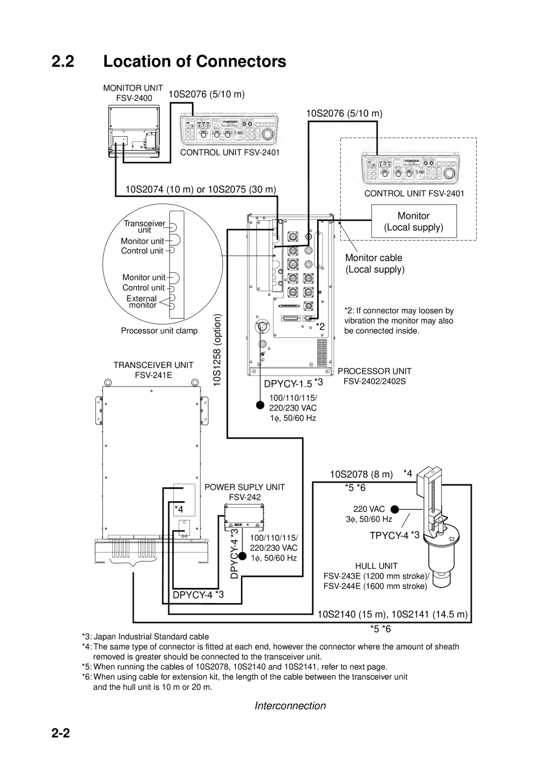
| *2: If connector may loosen by |
| (option) |
| |
| *2 | vibration the monitor may also | |
|
| ||
Processor unit clamp |
| be connected inside. | |
10S1258 |
| ||
TRANSCEIVER UNIT |
| ||
|
| PROCESSOR UNIT | |
|
|
| |
|
| 100/110/115/ |
|
|
| 220/230 VAC |
|
|
| 1φ , 50/60 Hz |
|
POWER SUPLY UNIT | ||
*4 |
| |
*3 | 100/110/115/ | |
4 | ||
220/230 VAC | ||
DPYCY- | ||
1φ , 50/60 Hz | ||
| ||
10S2078 (8 m) *4 ![]()
![]() *5 *6
*5 *6![]()
220 VAC
3φ , 50/60 Hz
HULL UNIT
![]()
10S2140 (15 m), 10S2141 (14.5 m)
*5 *6
*3: Japan Industrial Standard cable
*4: The same type of connector is fitted at each end, however the connector where the amount of sheath removed is greater should be connected to the transceiver unit.
*5: When running the cables of 10S2078, 10S2140 and 10S2141, refer to next page.
*6: When using cable for extension kit, the length of the cable between the transceiver unit and the hull unit is 10 m or 20 m.
Interconnection