2.5.4Connection
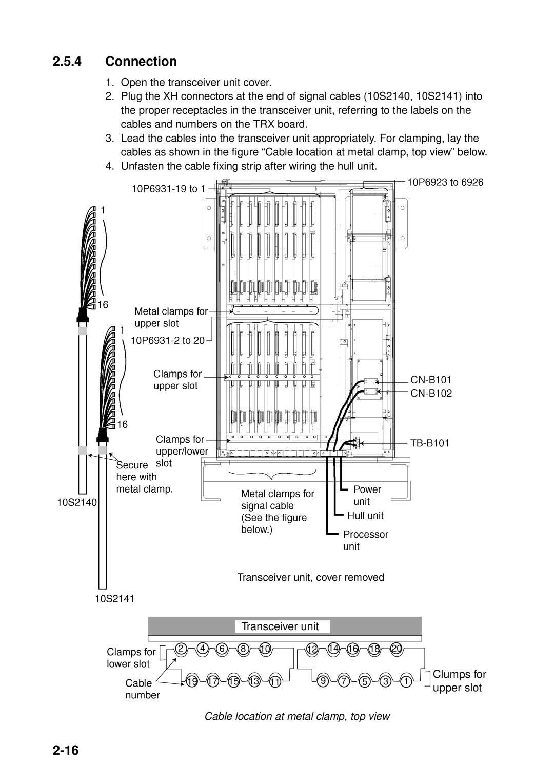
1.Open the transceiver unit cover.
2.Plug the XH connectors at the end of signal cables (10S2140, 10S2141) into the proper receptacles in the transceiver unit, referring to the labels on the cables and numbers on the TRX board.
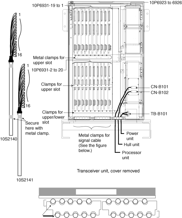
3.Lead the cables into the transceiver unit appropriately. For clamping, lay the cables as shown in the figure “Cable location at metal clamp, top view” below.
4.Unfasten the cable fixing strip after wiring the hull unit.
Transceiver unit
Clamps for | 2 | 4 | 6 |
| 8 | 10 | 12 | 14 | 16 | 18 |
| 20 |
|
|
|
|
|
|
|
|
|
|
|
|
|
| |
lower slot |
|
|
|
|
|
|
|
|
|
|
|
| Clumps for |
Cable |
| 19 | 17 | 15 | 13 | 11 | 9 |
| 7 | 5 | 3 | 1 | |
|
| upper slot | |||||||||||
number |
|
|
|
|
|
|
|
|
|
|
|
| |
|
|
|
|
|
|
|
|
|
|
|
|
|
Cable location at metal clamp, top view