Vertical Drilling Motor, Type GE752, GEK±91584D
2 X 6 X 20±1/2 |
|
|
(8 PIECES) |
|
|
| 50±1/2 |
|
ALL DIMENSIONS IN INCHES | ||
|
| 1 X 6 X 22 |
9±1/2 |
| (NO HOLE) |
|
| |
3 X 6 |
|
|
1 X 6 X 22 | 1 X 6 X 57±1/2 | |
(18 PIECES) |
| |
(2 PIECES) |
|
|
WITH HOLES |
|
|
2 X 6 X 24 | 1 X 6 X 22 |
|
(4 PIECES) | 2 SKIDS ± | |
| (18 PIECES) | |
| 3 X 6 X 57±1/2 | |
|
| |
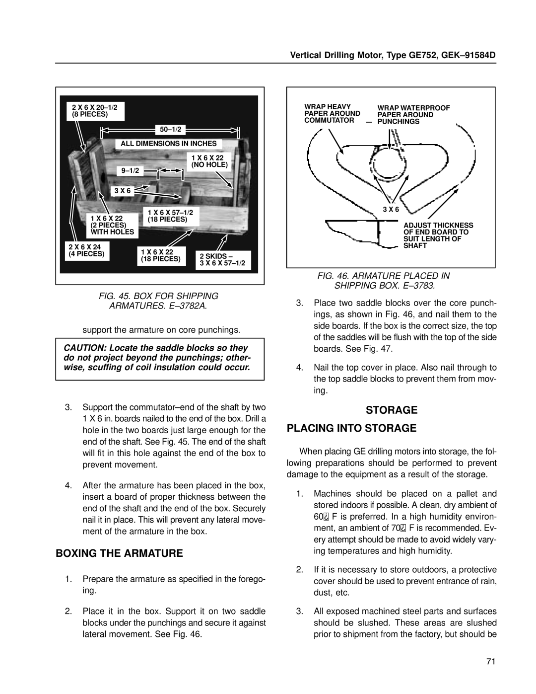
FIG. 45. BOX FOR SHIPPING
ARMATURES. E±3782A.
support the armature on core punchings.
CAUTION: Locate the saddle blocks so they do not project beyond the punchings; other- wise, scuffing of coil insulation could occur.
3.Support the commutator±end of the shaft by two 1 X 6 in. boards nailed to the end of the box. Drill a hole in the two boards just large enough for the end of the shaft. See Fig. 45. The end of the shaft will fit in this hole against the end of the box to prevent movement.
4.After the armature has been placed in the box, insert a board of proper thickness between the end of the shaft and the end of the box. Securely nail it in place. This will prevent any lateral move- ment of the armature in the box.
BOXING THE ARMATURE
1.Prepare the armature as specified in the forego- ing.
2.Place it in the box. Support it on two saddle blocks under the punchings and secure it against lateral movement. See Fig. 46.
WRAP HEAVY | WRAP WATERPROOF |
PAPER AROUND | PAPER AROUND |
COMMUTATOR | PUNCHINGS |
3 X 6
ADJUST THICKNESS
OF END BOARD TO
SUIT LENGTH OF
SHAFT
FIG. 46. ARMATURE PLACED IN
SHIPPING BOX. E±3783.
3.Place two saddle blocks over the core punch- ings, as shown in Fig. 46, and nail them to the side boards. If the box is the correct size, the top of the saddles will be flush with the top of the side boards. See Fig. 47.
4.Nail the top cover in place. Also nail through to the top saddle blocks to prevent them from mov- ing.
STORAGE
PLACING INTO STORAGE
When placing GE drilling motors into storage, the fol- lowing preparations should be performed to prevent damage to the equipment as a result of the storage.
1.Machines should be placed on a pallet and stored indoors if possible. A clean, dry ambient of
60![]() F is preferred. In a high humidity environ- ment, an ambient of 70 F is recommended. Ev- ery attempt should be made to avoid widely vary- ing temperatures and high humidity.
F is preferred. In a high humidity environ- ment, an ambient of 70 F is recommended. Ev- ery attempt should be made to avoid widely vary- ing temperatures and high humidity.
2.If it is necessary to store outdoors, a protective cover should be used to prevent entrance of rain, dust, etc.
3.All exposed machined steel parts and surfaces should be slushed. These areas are slushed prior to shipment from the factory, but should be
71
