Undercutting
See Fig. 28 for a diagram of proper undercut.
A sharp hacksaw blade may be used but caution must be observed since a dull blade or saw produces
Vertical Drilling Motor, Type GE752, GEK±91584D
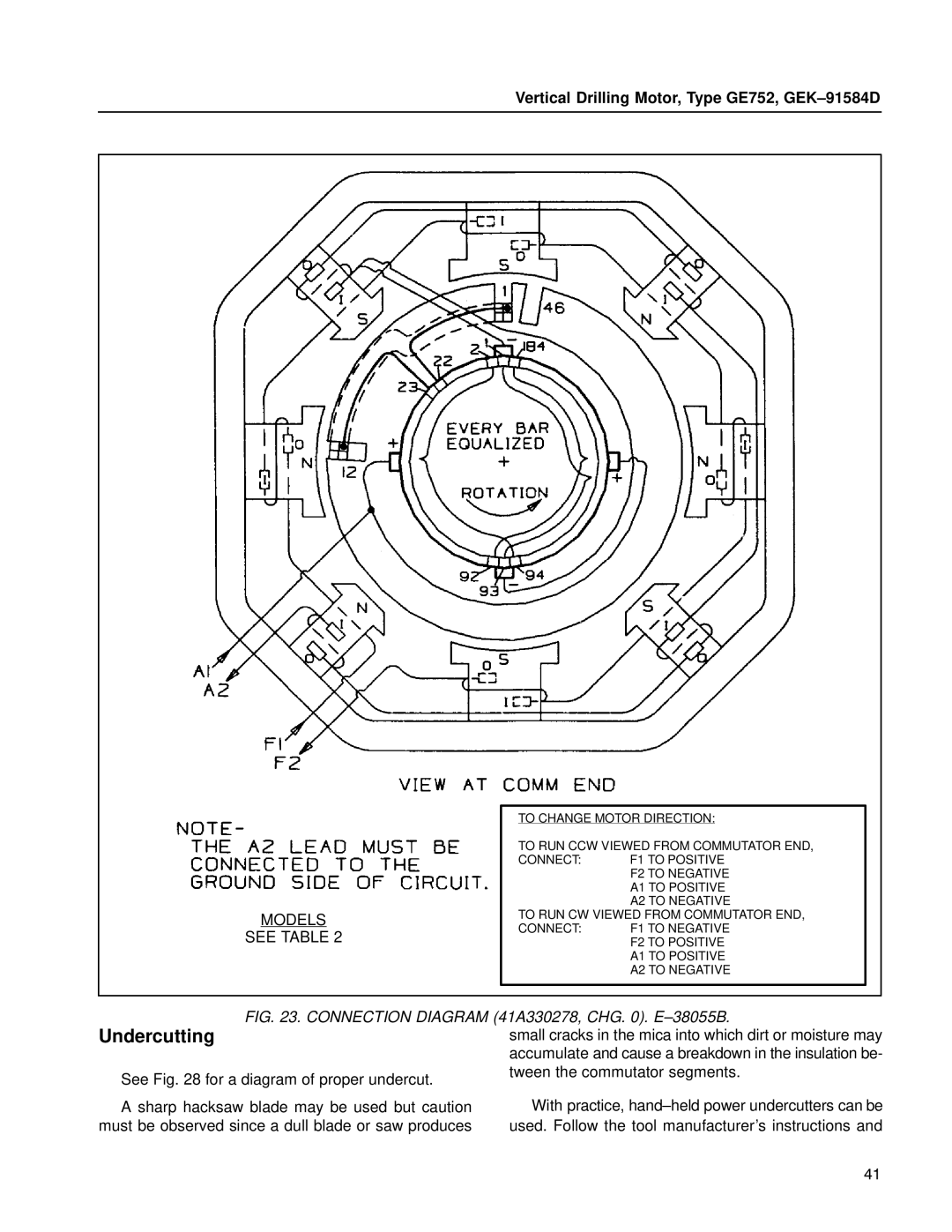
MODELS
SEE TABLE 2
TO CHANGE MOTOR DIRECTION:
TO RUN CCW VIEWED FROM COMMUTATOR END,
CONNECT: | F1 TO POSITIVE |
| F2 TO NEGATIVE |
| A1 TO POSITIVE |
| A2 TO NEGATIVE |
TO RUN CW VIEWED FROM COMMUTATOR END, | |
CONNECT: | F1 TO NEGATIVE |
| F2 TO POSITIVE |
| A1 TO POSITIVE |
| A2 TO NEGATIVE |
FIG. 23. CONNECTION DIAGRAM (41A330278, CHG. 0). E±38055B.
small cracks in the mica into which dirt or moisture may accumulate and cause a breakdown in the insulation be- tween the commutator segments.
With practice, hand±held power undercutters can be used. Follow the tool manufacturer's instructions and
41