GEK±91584D, Vertical Drilling Motor, Type GE752
MODELS
SEE TABLE 2, PAGE 20
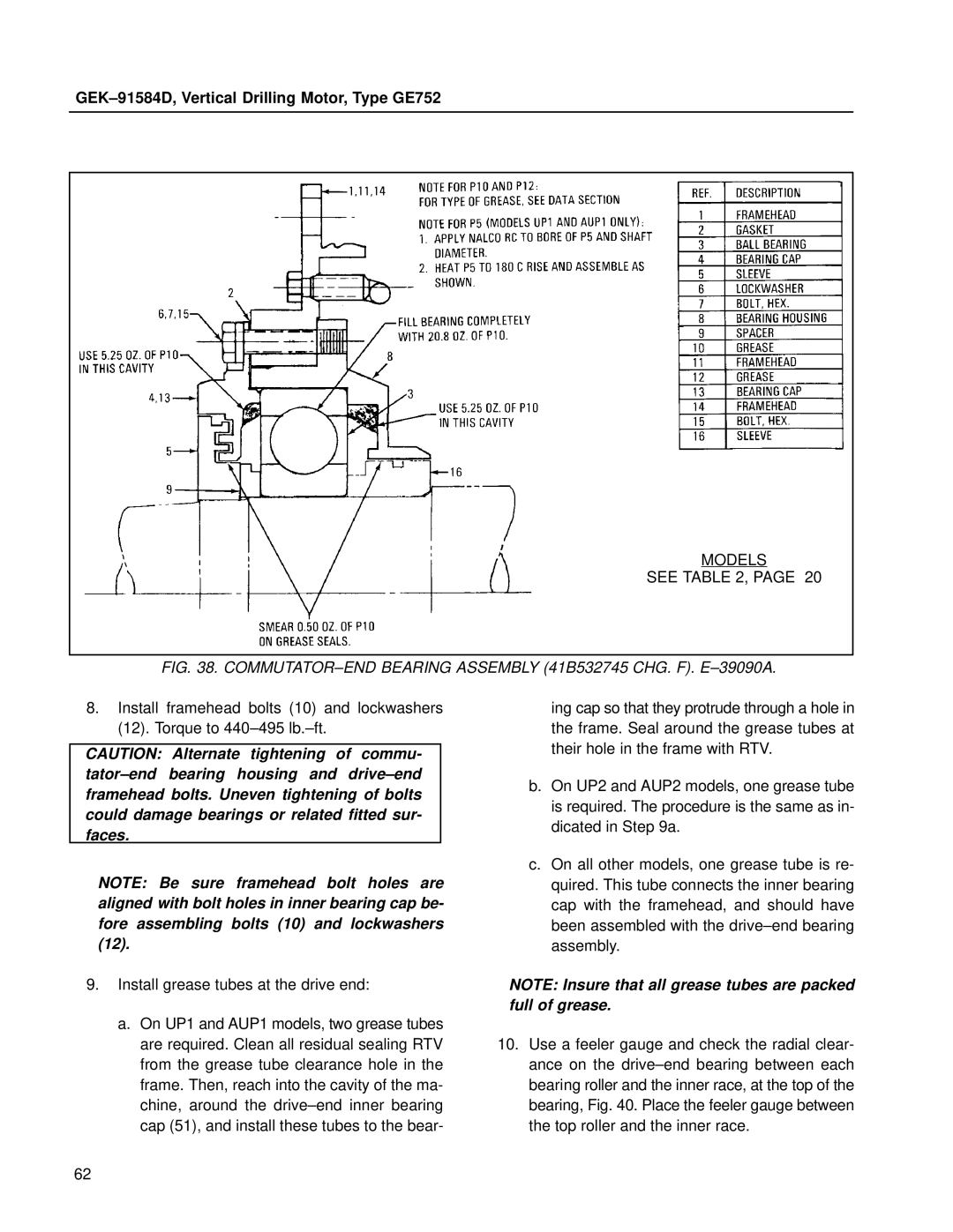
FIG. 38. COMMUTATOR±END BEARING ASSEMBLY (41B532745 CHG. F). E±39090A.
8.Install framehead bolts (10) and lockwashers (12). Torque to 440±495 lb.±ft.
CAUTION: Alternate tightening of commu- tator±end bearing housing and drive±end framehead bolts. Uneven tightening of bolts could damage bearings or related fitted sur- faces.
NOTE: Be sure framehead bolt holes are aligned with bolt holes in inner bearing cap be- fore assembling bolts (10) and lockwashers (12).
9.Install grease tubes at the drive end:
ing cap so that they protrude through a hole in the frame. Seal around the grease tubes at their hole in the frame with RTV.
b.On UP2 and AUP2 models, one grease tube is required. The procedure is the same as in- dicated in Step 9a.
c.On all other models, one grease tube is re- quired. This tube connects the inner bearing cap with the framehead, and should have been assembled with the drive±end bearing assembly.
NOTE: Insure that all grease tubes are packed full of grease.
a.On UP1 and AUP1 models, two grease tubes are required. Clean all residual sealing RTV from the grease tube clearance hole in the frame. Then, reach into the cavity of the ma- chine, around the drive±end inner bearing cap (51), and install these tubes to the bear-
10.Use a feeler gauge and check the radial clear- ance on the drive±end bearing between each bearing roller and the inner race, at the top of the bearing, Fig. 40. Place the feeler gauge between the top roller and the inner race.
62