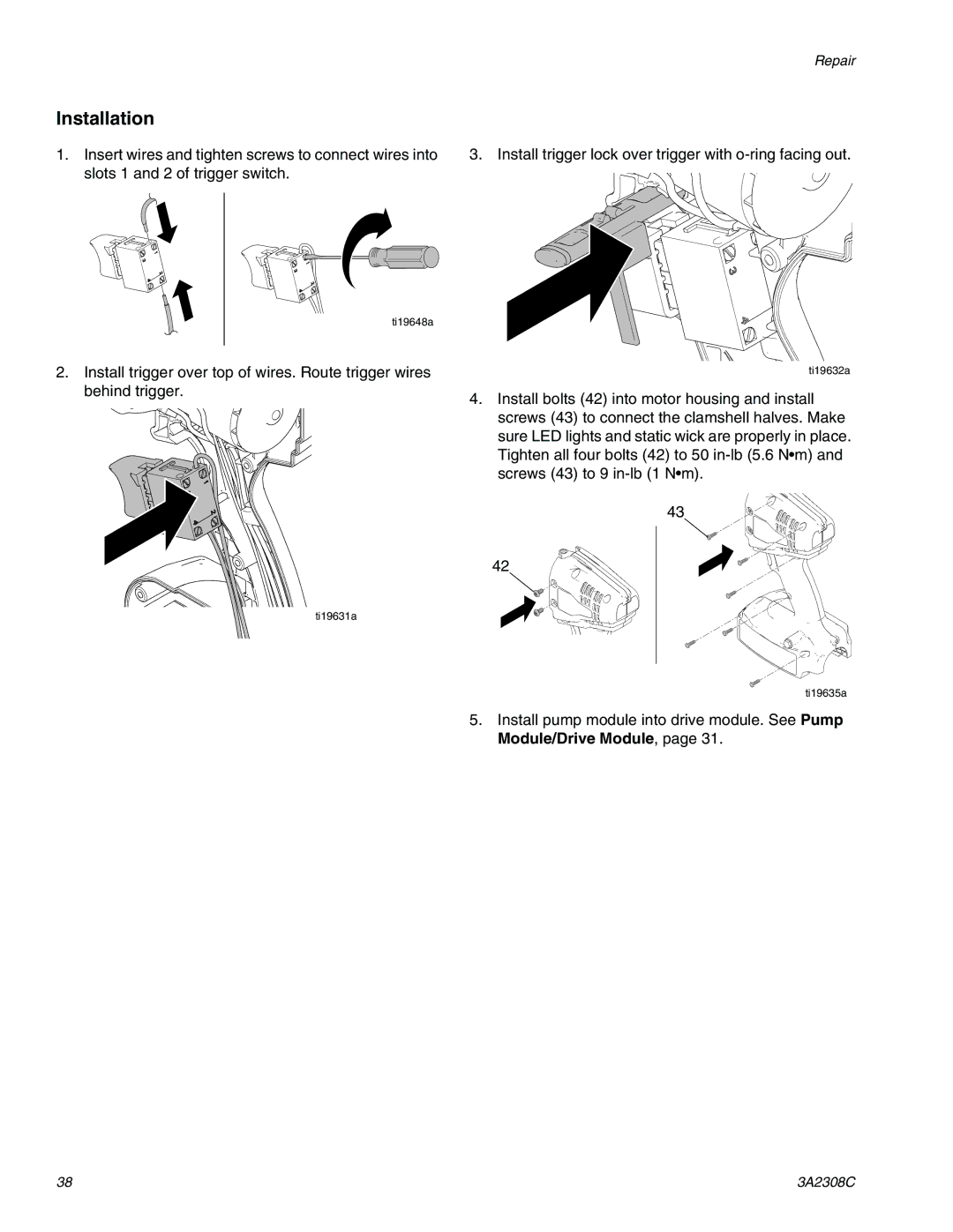
Installation
1.Insert wires and tighten screws to connect wires into slots 1 and 2 of trigger switch.
ti19648a
2.Install trigger over top of wires. Route trigger wires behind trigger.
ti19631a
Repair
3. Install trigger lock over trigger with o-ring facing out.
ti19632a
4.Install bolts (42) into motor housing and install screws (43) to connect the clamshell halves. Make sure LED lights and static wick are properly in place. Tighten all four bolts (42) to 50
43
42
ti19635a
5.Install pump module into drive module. See Pump Module/Drive Module, page 31.
38 | 3A2308C |