6.Fasten the 79" rear rail to the extension table with three
![]()
![]() x 3
x 3
Figure 15. Rear rail/table fastener locations.
7.Align the table and extension table with a straightedge (Figure 16), then tighten the fasteners in Figure 14 with a 5mm hex wrench and 13mm wrench.
Figure 16. Aligning main extension table.
8.Repeat the aligning procedure and tighten the fasteners in Figure 15 with a 6mm hex wrench and 13mm wrench.
9.Tighten the cap screws shown in Figure 13.
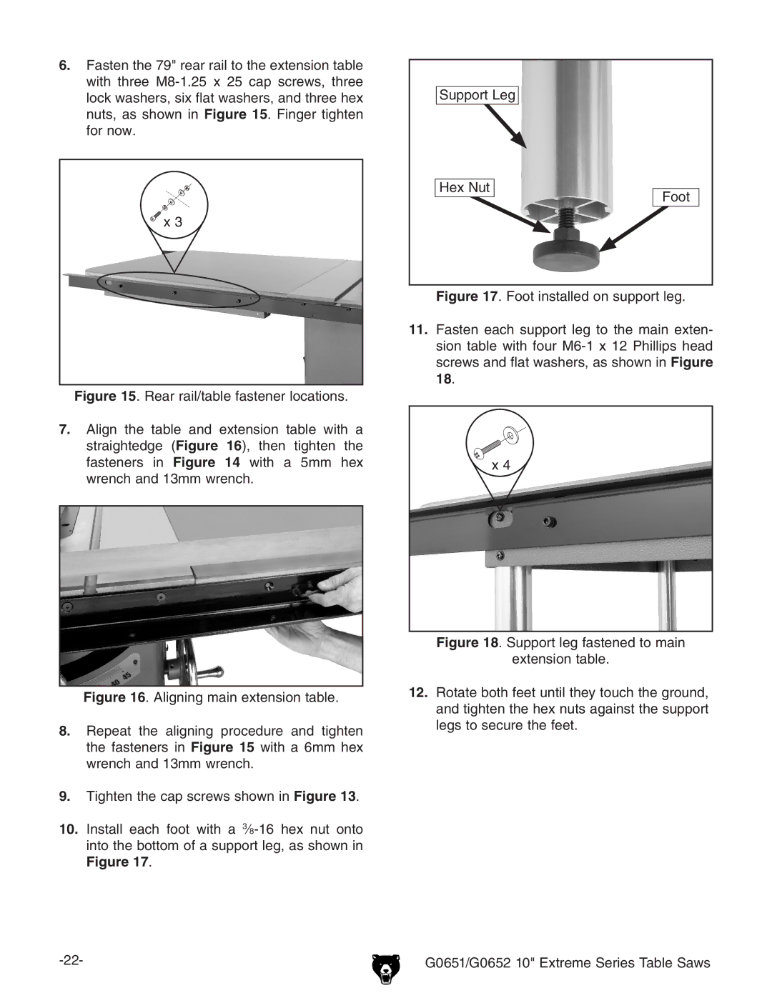
10.Install each foot with a 3⁄8-16 hex nut onto into the bottom of a support leg, as shown in
Figure 17.
Support Leg
Hex Nut | Foot |
|
Figure 17. Foot installed on support leg.
11.Fasten each support leg to the main exten- sion table with four M6-1 x 12 Phillips head screws and flat washers, as shown in Figure 18.
x 4