Miter Gauge |
|
Tools Needed | Qty |
Hex Wrench 2.5mm | 1 |
Phillips Head Screwdriver | 1 |
Machinist Square | 1 |
Adjustable Square | 1 |
Wrench 8mm | 1 |
To adjust the miter gauge so it is perpendicu- lar to the saw blade:
1.Slide the miter gauge into the miter gauge slot to the left of the blade.
2.Push in the shaft (Figure 84).
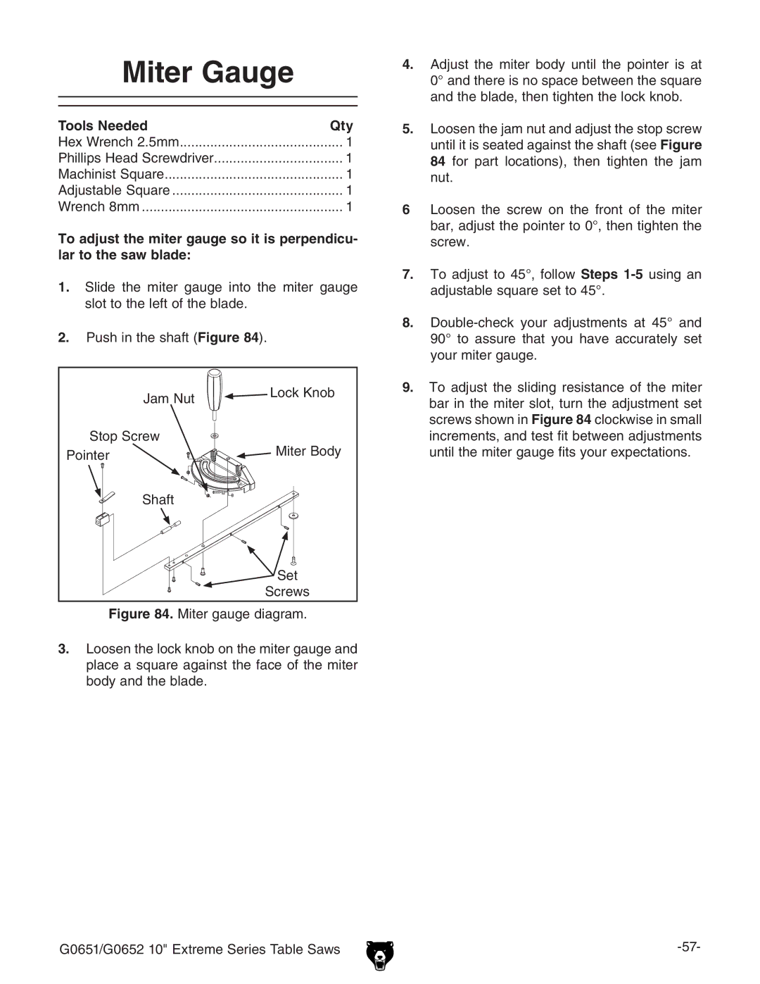
Jam Nut | Lock Knob | |
| ||
Stop Screw | Miter Body | |
Pointer | ||
| ||
Shaft |
| |
| Set | |
| Screws |
Figure 84. Miter gauge diagram.
3.Loosen the lock knob on the miter gauge and place a square against the face of the miter body and the blade.
4.Adjust the miter body until the pointer is at 0° and there is no space between the square and the blade, then tighten the lock knob.
5.Loosen the jam nut and adjust the stop screw until it is seated against the shaft (see Figure 84 for part locations), then tighten the jam nut.
6Loosen the screw on the front of the miter bar, adjust the pointer to 0°, then tighten the screw.
7.To adjust to 45°, follow Steps 1-5 using an adjustable square set to 45°.
8.Double-check your adjustments at 45° and 90° to assure that you have accurately set your miter gauge.
9.To adjust the sliding resistance of the miter bar in the miter slot, turn the adjustment set screws shown in Figure 84 clockwise in small increments, and test fit between adjustments until the miter gauge fits your expectations.
G0651/G0652 10" Extreme Series Table Saws |