5.Make sure the power cord and wires have slack between the strain relief and terminal connections so that they do not bind, then tighten the strain relief to secure the cord.
Note: The strain relief must be tightened against the outer jacket of the cord. Avoid
6.Test the strain relief to ensure it is properly tightened by pulling the cord from outside the box with
7.install a NEMA
8.Close and lock the main electrical box door.
To avoid unexpected
9.Connect the plug to the matching receptacle and power source as specified in Circuit Requirements for 220V on Page 15.
Test Run
Once the assembly is complete, test run your machine to make sure it runs properly and is ready for regular operation.
The test run consists of verifying:
•the motor powers up and runs correctly.
•The motor turns in the correct direction (machine is not wired out of phase).
•the safety features work correctly.
•the brake system works correctly.
•the cutting fluid system works correctly.
If, during the test run, you cannot easily locate the source of an unusual noise or vibration, stop using the machine immediately, then review Troubleshooting on Page 73.
Before starting the lathe, make sure you have performed the preceding assembly and adjustment instructions, and you have read through the rest of the manual and are familiar with the various functions and safety features on this machine. Failure to follow this warning could result in serious personal injury or even death!
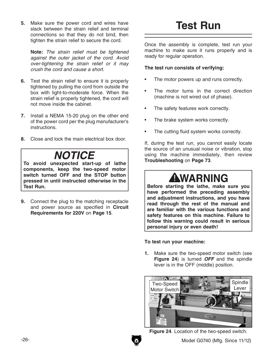
To test run your machine:
1.make sure the
|
| Spindle | |
| Lever | ||
Motor Switch |
| ||
|
| ||
|
|
|
