Manuals
/
Grizzly
/
Power Tools
/
Lathe
Grizzly
owner manual
Electrical Box, Electrical box wiring Model G0740 Mfg. Since 11/12
Models:
G0740
1
91
132
132
Download
132 pages
55.93 Kb
88
89
90
91
92
93
94
95
Troubleshooting
Specs
Install
Parts list
Thread Dial Chart
Machine Data Sheet
G9610-Test Indicator
Wiring
Warranty
Maintenance
Page 91
Image 91
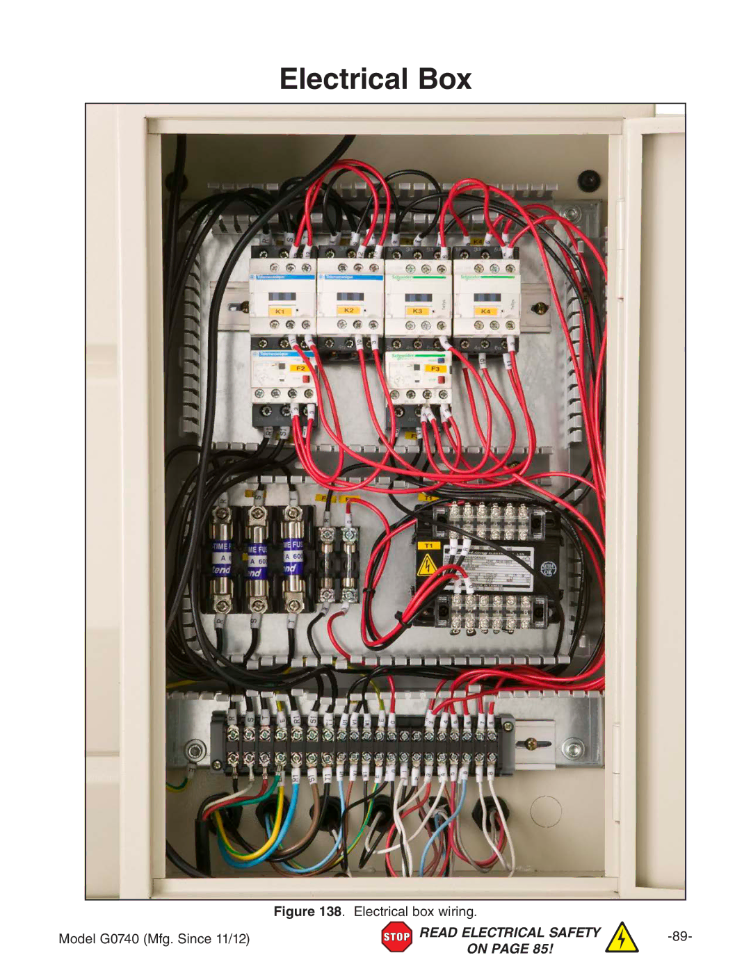
Electrical Box
Figure 138
. Electrical box wiring.
Model G0740 (Mfg. Since 11/12)
READ ELECTRICAL SAFETY
-89-
ON PAGE 85!
Page 90
Page 92
Page 91
Image 91
Page 90
Page 92
Contents
Model G0740 14 X 40 HIGH-PRECISION Toolroom Lathe
Page
Table of Contents
129
Maintenance
Machine Description Manual Accuracy
Introduction
Contact Info
Identification
Controls Components
Two-Speed Motor Switch
Headstock
Carriage
Control Panel
Tailstock
Safety Foot Brake
End Gears
Machine Data Sheet
Tailstock Info
Other Specifications
Safety Instructions for Machinery
Safety
Page
Additional Safety for Metal Lathes
Additional Chuck Safety
Circuit Requirements for
Power Supply
Availability
Full-Load Current Rating
50 ft
Grounding Instructions
Extension Cords
Minimum Gauge Size 12 AWG
To correct wiring that is out of phase
Correcting Phase Polarity Wiring
Unpacking
Setup
Needed for Setup
Preparation
Tool Box Inventory Figure Qty
Box 1 Figure Qty Steady Rest Assembly Installed
Pre-Installed Not Shown Qty
Inventory
Before cleaning, gather the following
Cleanup
Basic steps for removing rust preventative
Site Considerations
To lift and move the lathe
Lifting & Moving
Leveling
Leveling & Mounting
Lubricating Lathe
Assembly
Bolting to Concrete Floors
To connect the power cord to the lathe
Power Connection
Adding Coolant
Test run consists of verifying
Test Run
Stop
Cross Slide
Spindle Break-In
Factory adjustments that should be verified
Recommended Adjustments
Operation Overview
Operations
MEDIUM-SIZE, Heavy Chucks
Chuck & Faceplate Mounting Installation Removal Devices
To install the chuck
Chuck Installation
Registration Marks
Chuck Removal
To remove the chuck
Chuck Jaw Reversal
Scroll Chuck Clamping
To reverse 2-piece jaws
Mounting Workpiece
Jaw Chuck
To mount a non-concentric workpiece to the faceplate
Faceplate
Positioning Tailstock
Using Quill
Installing Tooling
Tailstock
Tools Needed Qty
Offsetting Tailstock
To install tooling in the tailstock
Removing Tooling
To align the tailstock to the spindle center- line
Aligning Tailstock to Spindle Centerline
To offset the tailstock
Items Needed Qty
Page
Mounting Dead Center in Spindle
Centers
Dead Centers
Live Centers
To mount a center in the tailstock
Removing Center from Spindle
Mounting Center in Tailstock
Removing Center from Tailstock
Mounting Workpiece Between Centers
Steady Rest
To install and use the steady rest
Carriage & Slide Locks
Follow Rest
Compound Rest Four-Way Tool Post
Installing Tool
Top View
Aligning Cutting Tool with Spindle Centerline
Below are two common methods
To align the cutting tool with the tailstock center
To set the micrometer stop
Adjustable Feed Stop
Micrometer Stop
Tools Needed Qty Hex Wrench 5mm
Spindle Speed
Manual Feed
Configuration Examples
Setting Spindle Speed
Setting Spindle Speed of 1600 RPM
Power Feed
Power Feed Controls
Setting Power Feed Rate of 0.18mm/rev
Setting Power Feed Rate
End Gears
Standard End Gear Configuration
To configure the end gears
Alternate Configuration
Headstock Threading Controls
Threading
Apron Threading Controls
Nut when required and prevent an apron crash
Thread Dial
Odd Numbered TPI
Thread Dial Chart
TPI Divisible By
Even TPI Not Divisible By
⁄4 or 3⁄4 Fractional TPI
Chip Drawer
27⁄8 TPI
Biological & Poison Hazard
Coolant System
T10439-4 Pc. Carbide Insert Ccmt Boring Bar Set
Accessories
G7978-Rotary Phase Converter
G9610-Test Indicator
G9611-Test Indicator
G9612-Test Indicator
Cleaning/Protecting
Maintenance
Schedule
Lubrication Task Frequency
Lubrication
To change the headstock oil
Quick-Change Gearbox
One-Shot Oiler
Apron
Ball Oilers & Oil Cup
Longitudinal Leadscrew
Handling & Care
Hazards
Coolant System Service
To add coolant
Adding Coolant
Changing Coolant
See Hazards on
To prepare the lathe for storage
Machine Storage
Motor & Electrical
Service
Troubleshooting
Symptom Possible Cause Possible Solution
Lathe Operation
Symptom Possible Cause Possible Solution
As necessary see
Compound Rest
Backlash Adjustment
Cross Slide
Gib Adjustment
Leadscrew End Play Adjustment
To remove leadscrew end play
Front saddle gib adjustment screw Carriage Lock Clamp
Belts
Half Nut Adjustment
To adjust the half nut
To adjust the V-belts
To adjust the brake and brake switch
Brake & Switch
Page
To replace the shear pin
Leadscrew Shear Pin Replacement
Shear Pin
Gap Installation
Gap Insert Removal Installation
Gap Removal
Wiring Safety Instructions
Wiring
Wiring Overview
Component location index Model G0740 Mfg. Since 11/12
Component Location Index
Safety Switch, To Work Lamp,
Electrical Cabinet Wiring
Electrical Box
Electrical box wiring Model G0740 Mfg. Since 11/12
Spindle Motor
Coolant Pump Wiring
To Electrical Cabinet
Speed Motor Switch
Spindle Switches
Control Panel Wiring
Power Connection
Headstock Cover
Parts
Headstock Controls
Headstock Controls Parts List
Gears
Headstock Internal Gears Parts List
Description
Headstock Transfer Gears
Gearbox Gears
Gearbox Gears Parts List
291 282 283 292 323 284 285 286
Gearbox Controls Parts List
Apron Front View
Apron Front View Parts List
Apron
Apron Rear View Parts List
Compound Rest & Tool Post
663
Saddle Top View
Saddle Top View Parts List
Saddle Bottom View
Bed Stop
Dial Indicator
Shafts
Bed
Bed & Shafts Parts List
Model G0740 Mfg. Since 11/12 115
Motor
Main Motor Parts List
118 Model G0740 Mfg. Since 11/12
Cabinets & Panels
Cabinets & Panels Parts List
Tailstock
Tailstock Parts List
Follow Rest
Electrical Cabinet & Control Panel
Accessories
Front Machine Labels
Rear & Side Machine Labels
Comments
Warranty Card
BOX BELLINGHAM, WA
Grizzly INDUSTRIAL, INC
Warranty & Returns
Order Hours a DAY
Top
Page
Image
Contents