Steady Rest
The steady rest supports long shafts and can be mounted anywhere along the length of the bedway.
Familiarize yourself with the steady rest compo- nents shown in Figure 56 to better understand its operation.
Finger
Adjustment
Knob
![]() Leaf
Leaf
Screw
![]() Finger
Finger
Roller
Clamp |
|
| |
Hex Nut | |||
Knob |
| ||
|
| ||
|
|
|
Figure 56. Steady rest components.
To install and use the steady rest:
1.DISCONneCT LAthe FROm POWER!
2.Thoroughly clean all mating surfaces, then place the steady rest base on the bedways so the triangular notch fits over the bedway prism.
3.position the steady rest where required to properly support the workpiece, then tighten the hex nut shown in Figure 56 to secure it in place.
Model G0740 (Mfg. Since 11/12)
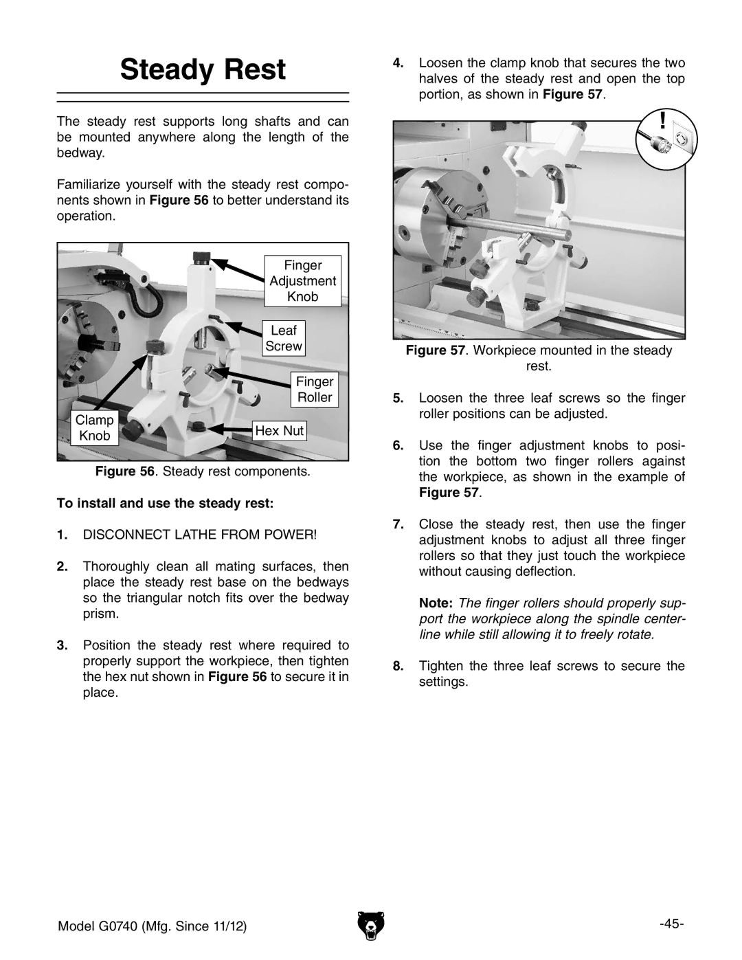
4.loosen the clamp knob that secures the two halves of the steady rest and open the top portion, as shown in Figure 57.
Figure 57. Workpiece mounted in the steady
rest.
5.Loosen the three leaf screws so the finger roller positions can be adjusted.
6.Use the finger adjustment knobs to posi- tion the bottom two finger rollers against the workpiece, as shown in the example of Figure 57.
7.Close the steady rest, then use the finger adjustment knobs to adjust all three finger rollers so that they just touch the workpiece without causing deflection.
Note: The finger rollers should properly sup- port the workpiece along the spindle center- line while still allowing it to freely rotate.