Compound Rest |
|
|
|
|
|
|
|
|
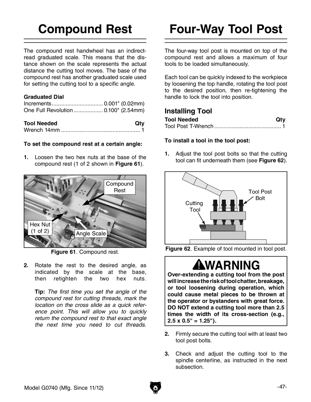
The compound rest handwheel has an indirect- read graduated scale. This means that the dis- tance shown on the scale represents the actual distance the cutting tool moves. The base of the compound rest has another graduated scale used for setting the cutting tool to a specific angle.
Graduated Dial |
|
Increments | 0.001" (0.02mm) |
One Full Revolution | 0.100" (2.54mm) |
Tool Needed | Qty |
Wrench 14mm | 1 |
To set the compound rest at a certain angle:
1.loosen the two hex nuts at the base of the compound rest (1 of 2 shown in Figure 61).
Compound |
Rest |
The
Each tool can be quickly indexed to the workpiece by loosening the top handle, rotating the tool post to the desired position, then
Installing Tool |
|
Tool Needed | Qty |
Tool Post | 1 |
To install a tool in the tool post: |
|
1.Adjust the tool post bolts so that the cutting tool can fit underneath them (see Figure 62).
Tool Post
Hex Nut |
|
(1 of 2) | Angle Scale |
|
Cutting
Tool
Bolt
Figure 61. Compound rest.
2.rotate the rest to the desired angle, as indicated by the scale at the base,
then retighten the two hex nuts.
Tip: The first time you set the angle of the compound rest for cutting threads, mark the location on the cross slide as a quick refer- ence point. This will allow you to quickly return the compound rest to that exact angle the next time you need to cut threads.
Model G0740 (Mfg. Since 11/12)
Figure 62. Example of tool mounted in tool post.
2.5x 0.5" = 1.25").
2.Firmly secure the cutting tool with at least two tool post bolts.
3.Check and adjust the cutting tool to the spindle centerline, as instructed in the next subsection.
