Tailstock |
|
|
Y | Z | AA |
|
| |
|
| AB |
|
| AC |
AF |
| AD |
| AE | |
|
|
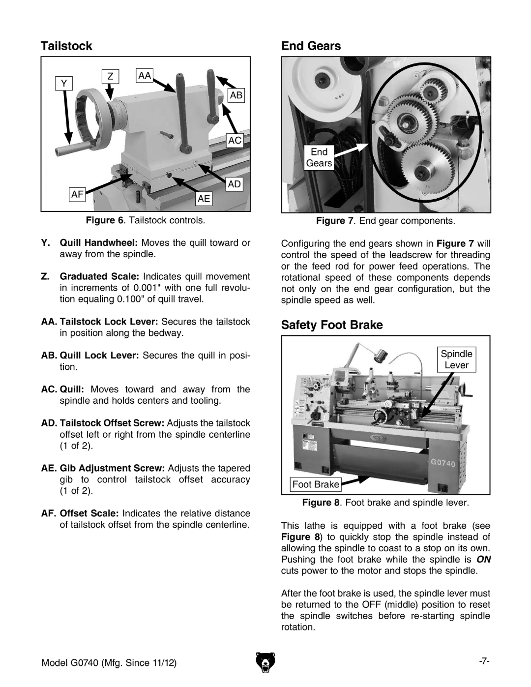
Figure 6. Tailstock controls.
Y.Quill Handwheel: Moves the quill toward or away from the spindle.
Z.Graduated Scale: Indicates quill movement in increments of 0.001" with one full revolu- tion equaling 0.100" of quill travel.
AA.Tailstock Lock Lever: Secures the tailstock in position along the bedway.
AB. Quill Lock Lever: Secures the quill in posi- tion.
AC. Quill: Moves toward and away from the spindle and holds centers and tooling.
AD. Tailstock Offset Screw: Adjusts the tailstock offset left or right from the spindle centerline (1 of 2).
AE. Gib Adjustment Screw: Adjusts the tapered gib to control tailstock offset accuracy (1 of 2).
AF. Offset Scale: Indicates the relative distance of tailstock offset from the spindle centerline.
Model G0740 (Mfg. Since 11/12)
End Gears
End
Gears
Figure 7. End gear components.
Configuring the end gears shown in Figure 7 will control the speed of the leadscrew for threading or the feed rod for power feed operations. The rotational speed of these components depends not only on the end gear configuration, but the spindle speed as well.
Safety Foot Brake
Spindle
Lever
Foot Brake