Gap Insert Removal
& Installation
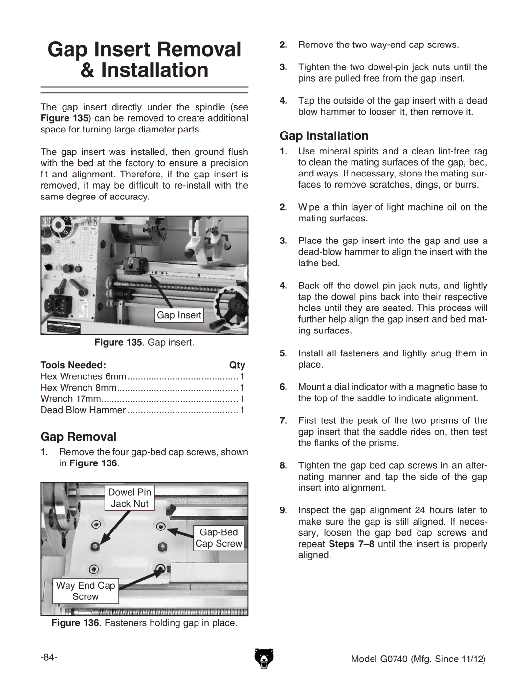
The gap insert directly under the spindle (see Figure 135) can be removed to create additional space for turning large diameter parts.
The gap insert was installed, then ground flush with the bed at the factory to ensure a precision fit and alignment. Therefore, if the gap insert is removed, it may be difficult to
Gap Insert
Figure 135. Gap insert.
Tools Needed: | Qty |
Hex Wrenches 6mm | .......................................... 1 |
Hex Wrench 8mm | 1 |
Wrench 17mm | 1 |
Dead Blow Hammer | 1 |
Gap Removal
1.Remove the four
Dowel Pin |
Jack Nut |
Cap Screw |
Way End Cap |
Screw |
Figure 136. Fasteners holding gap in place.
2.Remove the two way-end cap screws.
3.tighten the two dowel-pin jack nuts until the pins are pulled free from the gap insert.
4.tap the outside of the gap insert with a dead blow hammer to loosen it, then remove it.
Gap Installation
1.Use mineral spirits and a clean
2.Wipe a thin layer of light machine oil on the mating surfaces.
3.place the gap insert into the gap and use a
4.back off the dowel pin jack nuts, and lightly tap the dowel pins back into their respective holes until they are seated. This process will further help align the gap insert and bed mat- ing surfaces.
5.Install all fasteners and lightly snug them in place.
6.mount a dial indicator with a magnetic base to the top of the saddle to indicate alignment.
7.First test the peak of the two prisms of the gap insert that the saddle rides on, then test the flanks of the prisms.
8.tighten the gap bed cap screws in an alter- nating manner and tap the side of the gap insert into alignment.
9.inspect the gap alignment 24 hours later to make sure the gap is still aligned. If neces- sary, loosen the gap bed cap screws and repeat Steps
Model G0740 (Mfg. Since 11/12)