Manual Feed
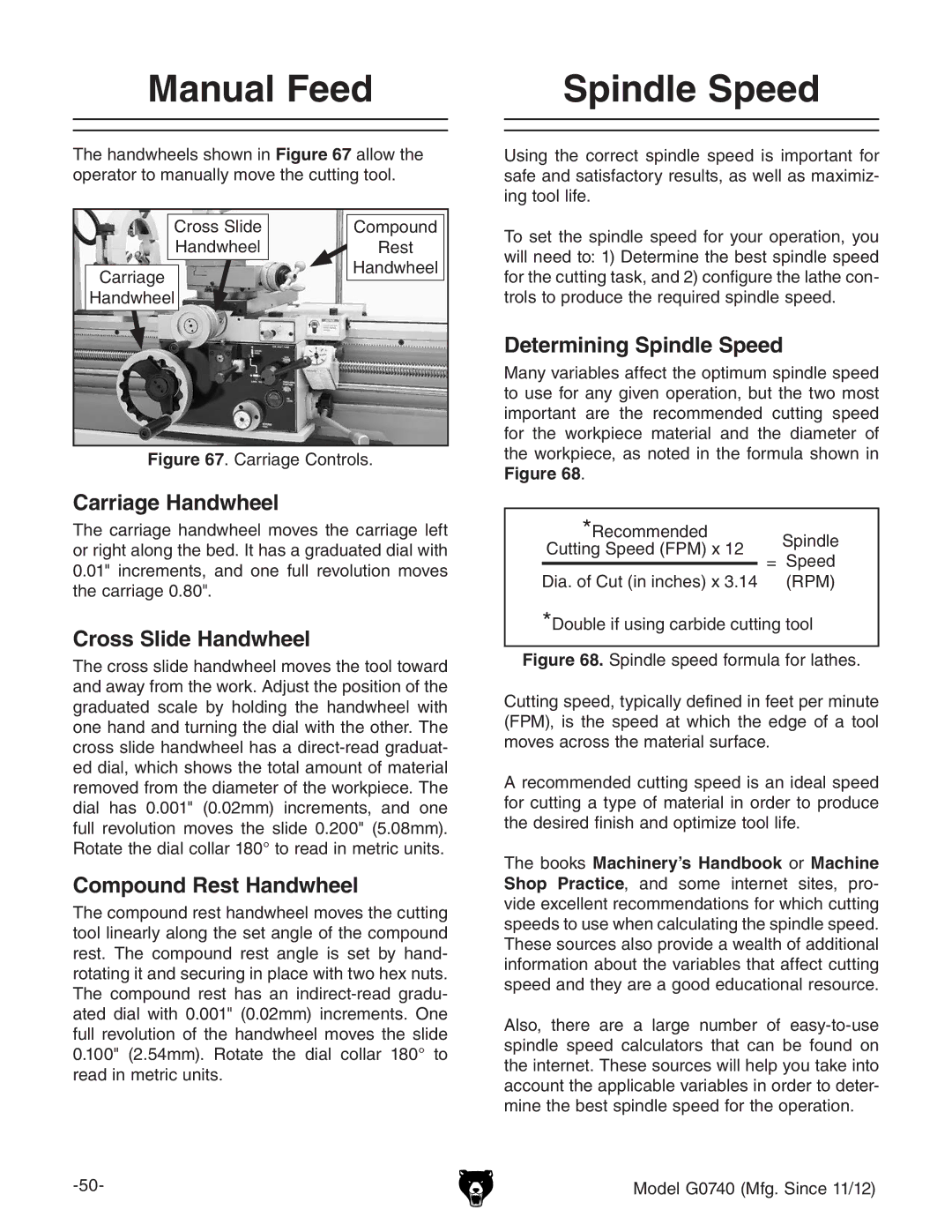
The handwheels shown in Figure 67 allow the operator to manually move the cutting tool.
Cross Slide | Compound |
Handwheel | Rest |
Carriage | Handwheel |
| |
Handwheel |
|
Figure 67. Carriage Controls.
Carriage Handwheel
The carriage handwheel moves the carriage left or right along the bed. It has a graduated dial with 0.01" increments, and one full revolution moves the carriage 0.80".
Cross Slide Handwheel
The cross slide handwheel moves the tool toward and away from the work. Adjust the position of the graduated scale by holding the handwheel with one hand and turning the dial with the other. The cross slide handwheel has a
Compound Rest Handwheel
The compound rest handwheel moves the cutting tool linearly along the set angle of the compound rest. The compound rest angle is set by hand- rotating it and securing in place with two hex nuts. The compound rest has an
Spindle Speed
Using the correct spindle speed is important for safe and satisfactory results, as well as maximiz- ing tool life.
To set the spindle speed for your operation, you will need to: 1) Determine the best spindle speed for the cutting task, and 2) configure the lathe con- trols to produce the required spindle speed.
Determining Spindle Speed
Many variables affect the optimum spindle speed to use for any given operation, but the two most important are the recommended cutting speed for the workpiece material and the diameter of the workpiece, as noted in the formula shown in Figure 68.
*Recommended |
| Spindle | ||
Cutting Speed (FPM) x 12 |
| |||
= | Speed | |||
|
| |||
|
| |||
Dia. of Cut (in inches) x 3.14 |
| (RPM) | ||
*Double if using carbide cutting tool