Manuals
/
Brands
/
Laundry Appliance
/
Clothes Dryer
/
GSI Outdoors
/
Laundry Appliance
/
Clothes Dryer
GSI Outdoors
PNEG-630
- page 77
1
77
121
121
Download
121 pages, 2.79 Mb
Portable Dryer Troubleshooting
76
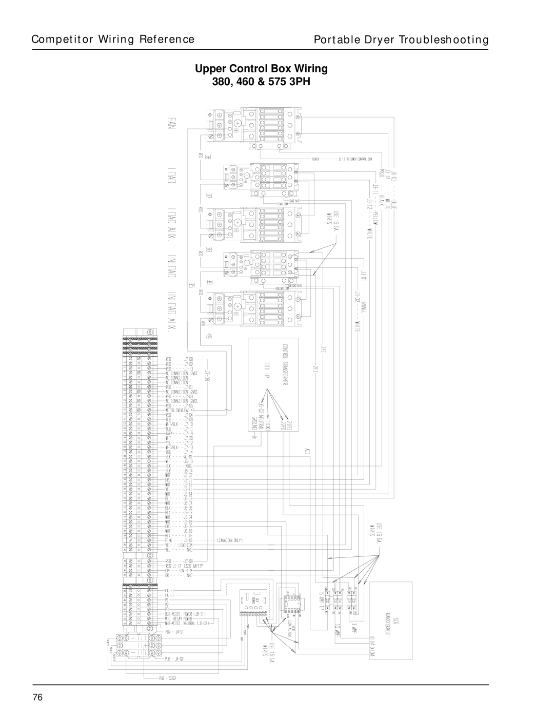
Upper Control Box Wiring
380, 460 & 575 3PH
Competitor Wiring Reference
Contents
Main
Page
Table Of Contents
Safety
WARNING! BE ALERT!
Safety Alert Symbol
Dryer Safety Instructions and Information
Safety
Page
Page
Use Caution in the Operation of this Equipment
Safety Precautions
READ THESE INSTRUCTIONS BEFORE OPERATION AND SERVICE SAVE FOR FUTURE REFERENCE
Date Employers Signature Employee
Safety Sign-Off Sheet
Safety Voltage Check Points
FAN # 123456
Programming Instructions for EMCS Grain Dryers
EMCS Display Board
Programming
Input/Output Board Identification
120 VOLT AC OUTPUTS12 VOLT DC INPUTS
Page
1100 Series Control Box Wiring
COLORVOLTAGE
1100EW98.PRT REV. DATE 4/10/98
J8-16
J8-9
Page
1200 Series Control Box Wiring
52 TOTAL TERMINALS
J8-16
J8-9
J8-18
Page
1100 Fan Lower Control Box Interconnect Strip
1200 Fan Lower Control Box Interconnect Strip
J9-3
I/O BOARD JUMPERS
45 - D01-0531 ENTRELEC TERMINALS 2 - D01-0533 END STOPS 1 - D01-0532 BLANK PROTECTOR ENDS
INSTALL J1-9 TO J5-6 INSTALL J5-2 TO J5-20 INSTALL J4-12 TO J5-10 INSTALL J9-1 TO J9-5
Upper Control Box External Wiring
Page
Page
Page
Grain & Plenum Hi-Limit Locations
FAN
11XX
2FNLMTSW98.PRT REV. DATE 4/5/98
Two Fan Plenum and Grain Limit Switch Wiring
FAN #1
FAN #2
12XX
Page
Rear Discharge Mercury Switch
Page
Page
Air Pressure Switch
INPUT/OUTPUT BOAR
D
TERMINAL LOCATION
PRESSURE SWITCH SAFETY CIRCUIT
HIGH
BLUE J1-13 AIRFLOW (N.O.)
BACKVIEW OF AIR SWITCH ASSEMBLY
Air Pressure Switch Drawing
BLUE J5-08 12VDC POSITIVE
Page
Out of Grain Safety Circuit Location
FAN
11XX
FRONT VIEW OF OPEN BOX
UP
Upper Junction Box Drawing
BLACK BLACK J5-04
BLACK
WHITE
TO LOAD MERCURY SWITCH
LEFT METER
RIGHT METER
ROLL SENSOR
Meter Roll Sensor Wiring
METER ROLL SENSOR
2 T-3 wires together.
Remove one meter roll board and tie the
1997 Dryers have only 1 meter roll board.
Board Meter Roll
IMPORTANT
Lower Junction Box Wiring
FAN
AND TEMPERATURE
TO REAR
DRIVE MOTOR
New Fenwal Board Wiring
Wiring Reference
IGNITOR
FLAME ROD
Fenwal Board Troubleshooting
Wiring Reference
Measure Flame Current
Flame Control Circuit
Fan Burner Circuit for Canadian Models Only
Page
Page
Page
Page
Page
Page
Page
Page
Page
SCR Drive Circuit
TO TERMINAL ON CONTACTOR
UPPER POWER STRIP
WITH POWER WIRES
SCR
11XX
REAR FRONT
E.M.C.S. PORTABLE DRYERS
Page
DC Drive Metering Roll System
Metering Roll Operation
Check the Motor
Check the SCR Drive Board
Fenwal Ignition System
Fenwal Ignition Operation
Fenwal Troubleshooting
Hints
Ignitor Tips
Hints
Metering Roll Sensors Metering Roll Sensor Operation
Air Pressure System
Airflow Operation
Troubleshooting: "Loss of Airflow"
Hints
Vapor High Temperature
Troubleshooting: Vapor High Temperature
Vapor High Limit Hints
Out Of Grain Warning
Possible Solution
Out of Grain Hints
Out Of Grain Warning Shutdown
Motor Overload Helpful Hints Motor Overload Shutdown
Page
220 Volt Single (1) Phase Power Drawing
Page
Page
Page
Page
Page
Page
Upper Control Box Internal Wiring
AC1
TERMINAL ON
UPPER STRIP
J6-15
Page
Page
Page
Series 100 Control Box Wiring
16 GA WIRES
100STRIP98.PRT REV. DATE 3/12/98
Page
Page
Page
Input/Output Board & Terminal Strip
Page
Page
Page
Page
Page
Page
Upper Control Box External Wiring
Input/Output Board 12 Volt
120 VOLT AC OUTPUT
12 VOLT DC INPUT
J1
3 AMP FUSE
J2 J5
Cpu Board Wiring
J7
J6
DISPLAY
MONITORING
Programing Instructions for Competitor Series Grain Dryers
Programmer Hook Up Diagram
THE PROGRAMMER
J7
J1 1
J8
Programming Instructions Using Palm Pilot
Programming Competitor
Prog rammin g Com petito r Drye r Usin g Palm Pilot
Back of Switch Panel Layout
YELLOW-3
BLACK J6-05 TO J6-11
WHITE J3-04 TO J6-17
RED J3-19 TO J6-16
Back of Switch Panel Wiring
J7-07
WHITE
RED
BLU
1XX
Air Switch Assembly
HIGH
WHITE/BLACK STRIP J7-10 AIRFLOW GROUND BLUE J7-09 AIRFLOW (N.O.)
BACKVIEW OF AIR SWITCH ASSEMBLY
IMPORTANT:
Air Switch Adjustment
Competitor Air Switch Adjustment
need to be full of grain so that the plenum can build up air pressure and close the air switch.
Air Switch assembly.
1XX
TO REAR
DRIVE MOTOR
TO SCR
AND TEMPERATURE
1XX
FRONT VIEW OF OPEN BOX
UP
Grain Temperature Sensor
1XX
Grain Sensor Testing
SENSORS COMP98.PRT
Temperature chart
See page 47 for resistance vs.
FIG.1
Grain Sensor
a Defective Grain Temperature Sensor
Grain Sensor
Procedure for Locating, Testing and Replacing a Defective Grain Temperature Sensor. (continued)
Sensor Chart
Resistance / Temperature Chart
Page
Page
Stern and Capacitor Diagram 10-17 HP 1Phase
OPERATION HINTS FOR COMPETITOR DRYERS
Operation Hints
OPERATION HINTS FOR COMPETITOR DRYERS
Operation Hints
Series 100 Error Conditions
Error Codes
Page
Heater Circuit
Webster
PART# HH-1093
SILICONE HIGH VOLTAGE IGNITION WIRES
GRN
Fan Burner Circuit For Canadian Models Only
INSIDE VIEW OF MERCOID
RELAY
MERCOID SAFETY
PRESSURE SWITCH
Series 100 LP 26"/28" Fan
PART# HH-1093
Webster
Series 100 Natural Gas 26"/28" Fan
PART# HH-1093
Webster
Series 100 LP 36"/42" Fan
PART# HH-1093
Webster
Series 100 Natural Gas 36"/42" Fan
PART# HH-1093
Webster
Warranty