29510_AVR745_Engelsk 30/10/06 9:31 Side 28
System Configuration
Once the settings have been made on the main video setup screen, you may either return to the main setup menu or proceed to the two Advanced Configuration setting menus. The options on those pages are set by your choice on the SOURCE TYPE line as shown above, but you may wish to change one or more of the set- tings to customize video presentation.
To return to the MAIN MENU, press the ¤ Navigation Button DF so that the on- screen ➞ cursor is pointing to BACK TO MASTER MENU and press the OK/Enter Button E on the TC 30 or the Set Button Q.
To change the settings on the ADVANCED CONFIGURATION menus, press the ¤ Navigation Button DF so that the on- screen ➞ cursor is pointing to ADVANCED CONFIG SET and press the Set Button Q. The first page of the ADVANCED CONFIGURATION menus (Figure 6a) will appear
Advanced Configuration Settings
The Advanced Configuration Settings may be used to change the individual items that make up the default profile for each video input. You may change none, one or as many of the settings as you wish to create the
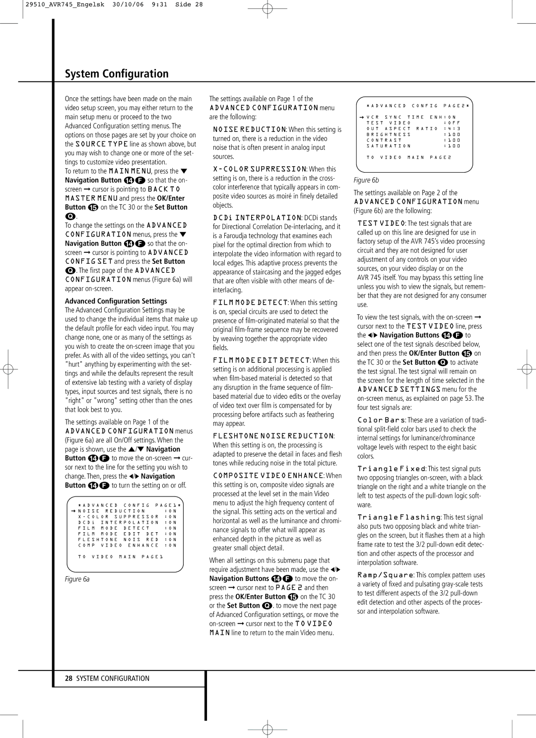
The settings available on Page 1 of the ADVANCED CONFIGURATION menus (Figure 6a) are all On/Off settings. When the page is shown, use the ⁄/¤ Navigation Button DF to move the
* A D V A N C E D | C O N F I G P A G E 1 * | |
→ N O I S E R E D U C T I O N | : O N | |
X - C O L O R | S U P P R E S S O R | : O N |
D C D i I N T E R P O L A T I O N | : O N | |
F I L M M O D E | D E T E C T | : O N | |
F I L M M O D E | E D I T | D E T : O N | |
F L E S H T O N E | N O I S | R E D : O N | |
C O M P V I D E O E N H A N C E : O N
T O V I D E O M A I N P A G E 1
Figure 6a
The settings available on Page 1 of the
ADVANCED CONFIGURATION menu are the following:
NOISE REDUCTION: When this setting is turned on, there is a reduction in the video noise that is often present in analog input sources.
DCDi INTERPOLATION: DCDi stands for Directional Correlation
FILM MODE DETECT: When this setting is on, special circuits are used to detect the presence of
FILM MODE EDIT DETECT: When this setting is on additional processing is applied when
FLESHTONE NOISE REDUCTION: When this setting is on, the processing is adapted to preserve the detail in faces and flesh tones while reducing noise in the total picture.
COMPOSITE VIDEO ENHANCE: When this setting is on, composite video signals are processed at the level set in the main Video menu to adjust the high frequency content of the signal. This setting acts on the vertical and horizontal as well as the luminance and chromi- nance signals to offer what will appear as enhanced depth in the picture as well as greater small object detail.
When all settings on this submenu page that require adjustment have been made, use the ‹/› Navigation Buttons DF to move the on- screen ➞ cursor next to PAGE 2 and then press the OK/Enter Button E on the TC 30 or the Set Button Q. to move the next page of Advanced Configuration settings, or move the
* A D V A N C E D C O N F I G | P A G E 2 * | ||
→ V C R | S Y N C | T I M E E N H : O N | |
T E S T V I D E O | : O F F | ||
O U T | A S P E C T R A T I O | : 4 : 3 | |
B R I G H T N E S S | : 1 0 0 | ||
C O N T R A S T |
| : 1 0 0 | |
S A T U R A T I O N | : 1 0 0 | ||
T O V I D E O M A I N P A G E 2
Figure 6b
The settings available on Page 2 of the ADVANCED CONFIGURATION menu (Figure 6b) are the following:
TEST VIDEO: The test signals that are called up on this line are designed for use in factory setup of the AVR 745’s video processing circuit and they are not designed for user adjustment of any controls on your video sources, on your video display or on the
AVR 745 itself. You may bypass this setting line unless you wish to view the signals, but remem- ber that they are not designed for any consumer use.
To view the test signals, with the
Color Bars: These are a variation of tradi- tional
Triangle Fixed: This test signal puts two opposing triangles
Triangle Flashing: This test signal also puts two opposing black and white trian- gles on the screen, but it flashes them at a high frame rate to test the 3/2
Ramp/Square: This complex pattern uses a variety of fixed and pulsating
28SYSTEM CONFIGURATION