Heat CONTROLLER, INC
Contents
Functions
Indoor Unit
Auto Wind
Remote Controller
Operation Owoff Operation Mode Selection
Fan Speed Selection
Air Circulation
Product SpecificationsCooling Only
Power Supply 17Z,-W
Oumw 1 ,260
Product SpecificationsCooling & Heating
Tubing hole cover
Jzý, Installation plate
Indoor Unit
9k, 12k 18k, 24k
Outdoor Unit
Gas side
Model DIM
Refrigeration Cycle Diagram
Cooling Only Models
Heat
Cooling & Heating Models
Camay a Heating
Evaporator I / \
MSS-012, MSS-018, MS18, MSS-024, MSF4424
Indoor Wiring Diagram
Indoor Wiring Diagram
Iroom
18k 24k
Outdoor Unit Cooling Only Models
9k, 12k
LO.a
12k 18k 24k
Function of main control
Time delay Safety Control
Cooling Operation Mode
Airflow Direction Control
Auto Operation Electronic control mode
Intake AIR Temp Setting TEMP. +1F
Setting TEMP. -10F
MODE2 MODE3 MODE4 Modes
Modeo
MODE1rStart
End
Selecting Low
Soft Dry Operation Mode
Intake AIR TE
OFF Compressor
Heating Operation Modeonly Heating Model
Intake AIR Temp Setting TEMP. +60F
Setting Temp
Indoor
Defrost OFF
Rý u
Pipe Temp
Defrost on
Cooling or Heating Mode with Sleep Mode Auto Control
Setting TEMP. -1F
Crank Case Heater Coil Controlonly Heating model
Setting Temp
Forced Operation
ICJ
Indoor
Outdoor
Buzzer Sound
Display Function
Self-diagnosis Function
Diagnosis
When connecting refrigerant tubing
Installation
Is toxic when burned
When servicing
Roof Top Installations
Selection of the best location
Piping length and the elevation
Wire or gas line can cause death or injury
Indoor Unit Installation
Avoid areas where electrical wiring, conduits or
Lower left and right side of Installation Plate
Started Poo
Piping and Drainage of Indoor Unit
Preparation of Pipings
113 H IW-0
Connection of Pipings
For right rear piping
Llj
5kgm39.8ft.ibs
For the left pipings
Indoor unit installation
Insert the connecting cable into the indoor unit
Tape the tubing, drain hose and the connecting
Installation plate. Engage the two hooks of the rear
Drain hose Taping
Connecting Pipings and the cable to Outdoor unit
Connecting the pipings to the Outdoor unit
Connection of the cable
Terminals and fasten the wire tightly with the fixing screw
2sanoev
Checking the Drainage
Connect the cable to the indoor unit
Attach the Grille onto the cabinet
Bwid
Forming the pipings
Page
Page
Temperature, Pressure, Ampere Chan
Settfemont of Outdoor Unit
Evaluation of theperformance
Sleep Mode Auto Button
Name and Function-Remote Controller
MG OFF Timer Button
Operation display
Qs Operation Mode Selection Button
Start/Stop Button
Remove the securing screws
Be careful not to lose the clip when reassem- bling
Cooling & Heating
To remove the Control Box
Remove 2 securing screws
Page
To remove the Grille from the Chassis
To remove the Control Box
Remove three screws fixing control box and motor
To remove the Discharge Grille
To remove the Evaporator
Unhook the tab on the left inside edge
To remove the Cross-Flow Fan
To remove the Fan Motor
Cycle Troubleshooting Guide
Trouble analysis
Cause of Trouble
Display PWB Assy Check Connector related to CN-DC/DC
Turn off Main Power Cý After 10 seconds
Connector related to CN-POWER Connector related to CN-FAN
Does beeping sound is made from the Indoor Unit?
Product Is not operate with the remote controller
R751K C711000PF Micom PIN Check Receiver Assy
Turn on Main Power
Compressor/Outdoor Fan are unable to drive
When Indoor Fan does not operate
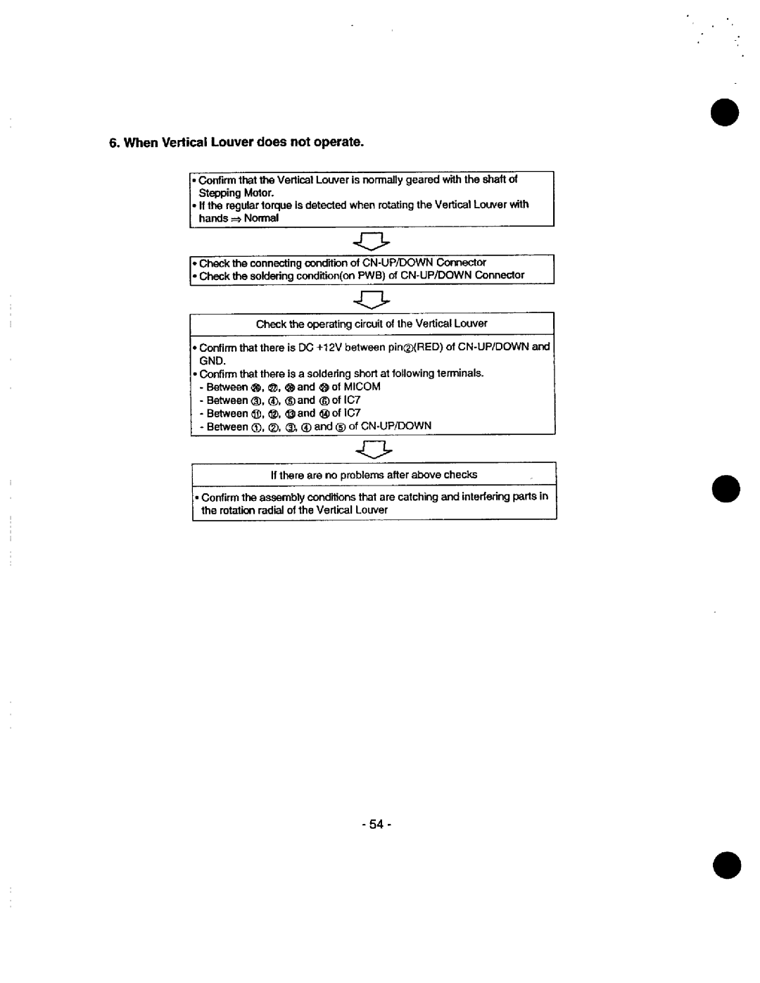
When Vertical Louver does not operate
When a comunication error occurs
Operation indicator of Indoor unit blinks five times
CN-UP/DOWN
Phenomena in case of connecting error
Indoor Unit
CN-TH
Outdoor Unit
CN-POWER RY-COMP
+0 , ý
CN-TRANS CN-FAN
Voltage of Connectors according to Indoor Fan Speed
Electronic Control Device
Optional Function
Main PWB ASSYOutdoor Unit
Optional Function Model
1OK
ASM
18k, 24k
LDt ftn
LD2 LD4
Schematic Diagram
Page
BA ýJ
Heat OTY Remark
Plate Installation
Remote Controller
Parts Name Controller
Indoor Unit18k, 24k
Parts Name
Motor Assy Chassis Assy
7DDD \ , \
Tom, .ý M m mm
Reversing Valve Reversing Coil
9k, 12k
Base Weld ASM Condenser Compressor ASM
Front Panel Assy
31 CAP
Barrier
TOP Cover ASM Rear Panel
Capillary Final ASM HEATERCRANK-CASE1 Heat QTY Remark
Outdoor Unit18k
`Ty
L8k
MSS-018A MSH-018A
171
Reversing Coil QTY Remark
PWB ASSY, Main SH-CAPACITOR
Clamp Capacitor Controller Assy Check Valve CAPILLARY, Bent
PANEL, Rear
CAPILLARY, Bent Panel Cover Control
29 CAP
2021-0024
9O2k
Remark R means service parts
ICJ No
MSS-009B MSS-012B 2021-0001
2021-0001 2021-0074 2010-0003 2021-0069 2021-0005
Plate Installation Holder Tube Motor Assy Chassis Assy
MSS-0188 MSH-018B
FAN Assy Cross
Service VALVE1/4 Service VALVE112
GQ 21k
Final ASM
TOP Cover ASM
Capillary
HEATERCRANK-CASE
High Pressure S/W
Reversing Valve
FAN Motor
2021-0024 I`J
MSS-018A MSH-018A
Support Valve High Pressure S/W Reversing Coil
SAT City Remark
PWBASSY,MAIN
2021-0021 2050-0001
UTY Remark
2035-0004 2035-0006
Extra FAN Barrier ASM
Heat CONTROLLER, INC