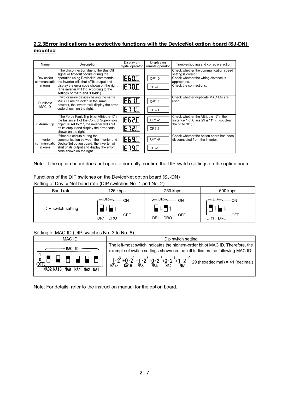
2.2.3Error indications by protective functions with the DeviceNet option board
Name | Description | Display on | Display on | |
digital operator | remote operator | |||
| If the disconnection due to the | |||
|
|
| ||
DeviceNet | signal or timeout occurs during the |
|
| |
operation using DeviceNet commands, |
| |||
communicatio | the inverter will shut off its output and |
|
| |
n error | display the error code shown on the right. |
| ||
| (The inverter will trip according to the |
| ||
|
|
| ||
| settings of "p45" and "P048".) |
|
| |
| If two or more devices having the same |
|
| |
Duplicate | MAC ID are detected in the same |
| ||
network, the inverter will display the error |
|
| ||
MAC ID |
|
| ||
code shown on the right. |
| |||
|
| |||
|
|
| ||
| If the Force Fault/Trip bit of Attribute 17 in |
| ||
| the Instance 1 of the Control Supervisory |
| ||
External trip | object is set to "1", the inverter will shut |
|
| |
| off its output and display the error code |
| ||
| shown on the right. |
|
| |
| If timeout occurs during the |
| ||
Inverter | communication between the inverter and |
| ||
communicatio | DeviceNet option board, the inverter will |
|
| |
n error | shut off its output and display the error |
| ||
| code shown on the right. |
|
|
Troubleshooting and corrective action
Check whether the communication speed setting is correct.
Check whether the wiring distance is appropriate.
Check the connections.
Check whether duplicate MAC IDs are used.
Check whether the Attribute 17 in the Instance 1 of Class 29 is "1". (If so, clear the bit to "0".)
Check whether the option board has been disconnected from the inverter.
Note: If the option board does not operate normally, confirm the DIP switch settings on the option board.
Functions of the DIP switches on the DeviceNet option board
Setting of DeviceNet baud rate (DIP switches No. 1 and No. 2)
Baud rate |
|
|
| 125 kbps |
|
|
| 250 kbps |
|
|
|
| 500 kbps | ||||||||
|
|
| DR | ON |
|
|
| DR | ON |
|
|
| DR | ON | |||||||
DIP switch setting |
|
|
|
|
|
|
|
|
|
|
|
|
|
|
| ↑ |
|
|
| ||
|
|
| ↓ |
| ↓ | OFF |
|
|
| ↓ |
| ↑ | OFF |
|
|
|
| ↓ | OFF | ||
|
|
|
|
|
|
|
|
| |||||||||||||
|
|
|
|
|
| ||||||||||||||||
|
|
|
|
|
|
|
|
|
|
|
|
|
|
|
|
|
|
| |||
| DR1 DRO |
| DR1 DRO |
| DR1 DRO | ||||||||||||||||
|
|
|
|
|
| ||||||||||||||||
|
|
|
|
|
|
|
|
|
|
|
|
|
|
|
|
|
|
|
|
|
|
Setting of MAC ID (DIP switches No. 3 to No. 8)
MAC ID | Dip switch setting | ||
|
|
| The |
|
|
| example of switch settings shown on the left indicates the following MAC ID: |
|
|
| = 29 (hexadecimal) = 41 (decimal) |
|
|
|
|
Note: For details, refer to the instruction manual for the option board.
2 - 7
