1.2 Precautions for Data Setting
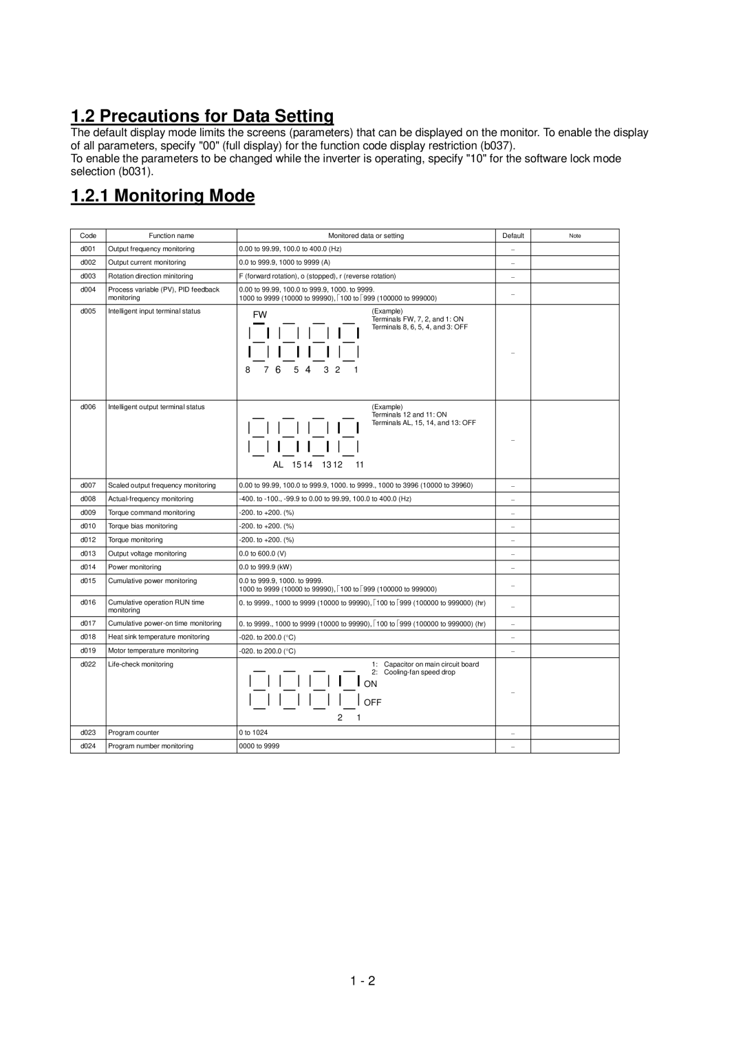
The default display mode limits the screens (parameters) that can be displayed on the monitor. To enable the display of all parameters, specify "00" (full display) for the function code display restriction (b037).
To enable the parameters to be changed while the inverter is operating, specify "10" for the software lock mode selection (b031).
1.2.1 Monitoring Mode
Code | Function name |
|
|
|
|
|
|
|
|
|
|
|
|
| Monitored data or setting | Default | Note | |||||||
|
|
|
|
|
|
|
|
|
|
|
|
|
|
|
|
|
|
|
|
|
|
| ||
d001 | Output frequency monitoring | 0.00 to 99.99, 100.0 to 400.0 (Hz) |
|
|
|
|
|
|
| |||||||||||||||
|
|
|
|
|
|
|
|
|
|
|
|
|
|
|
|
|
|
|
|
|
|
|
| |
d002 | Output current monitoring | 0.0 to 999.9, 1000 to 9999 (A) |
|
|
|
|
|
|
|
|
| |||||||||||||
|
|
|
|
|
|
|
|
|
|
|
|
|
|
|
|
|
|
|
|
|
| |||
d003 | Rotation direction minitoring | F (forward rotation), o (stopped), r (reverse rotation) |
|
|
| |||||||||||||||||||
|
|
|
|
|
|
|
|
|
|
|
|
|
|
|
|
|
|
|
|
|
| |||
d004 | Process variable (PV), PID feedback | 0.00 to 99.99, 100.0 to 999.9, 1000. to 9999. |
|
|
| |||||||||||||||||||
| monitoring | 1000 to 9999 (10000 to 99990), 100 to 999 (100000 to 999000) |
|
| ||||||||||||||||||||
|
|
|
|
|
|
|
|
|
|
|
|
|
|
|
|
|
|
|
|
|
|
|
| |
d005 | Intelligent input terminal status |
|
| FW |
|
|
|
|
|
|
|
|
|
|
|
|
|
|
| (Example) |
|
| ||
|
|
|
|
|
|
|
|
|
|
|
|
|
|
|
|
|
|
| Terminals FW, 7, 2, and 1: ON |
|
| |||
|
|
|
|
|
|
|
|
|
|
|
|
|
|
|
|
|
|
|
|
| Terminals 8, 6, 5, 4, and 3: OFF |
|
| |
|
|
|
|
|
|
|
|
|
|
|
|
|
|
|
|
|
|
|
|
|
|
| ||
|
|
|
|
|
|
|
|
|
|
|
|
|
|
|
|
|
|
|
|
|
|
|
|
|
|
|
|
|
|
|
|
|
|
|
|
|
|
|
|
|
|
|
|
|
|
|
|
|
|
|
|
|
|
|
|
|
|
|
|
|
|
|
|
|
|
|
|
|
|
|
|
|
|
|
|
|
|
|
|
|
|
|
|
|
|
|
|
|
|
|
|
|
|
|
|
|
|
|
|
|
|
|
|
|
| 6 |
|
|
| 4 |
|
|
|
|
|
|
|
|
|
|
|
| ||
|
| 8 | 7 |
| 5 | 3 |
| 2 |
| 1 |
|
|
|
|
| |||||||||
|
|
|
|
|
|
|
|
|
|
|
|
|
|
|
|
|
|
|
|
|
|
|
| |
d006 | Intelligent output terminal status |
|
|
|
|
|
|
|
|
|
|
|
|
|
|
|
|
|
|
| (Example) |
|
| |
|
|
|
|
|
|
|
|
|
|
|
|
|
|
|
|
|
|
|
|
| Terminals 12 and 11: ON |
|
| |
|
|
|
|
|
|
|
|
|
|
|
|
|
|
|
|
|
|
|
|
| Terminals AL, 15, 14, and 13: OFF |
|
| |
|
|
|
|
|
|
|
|
|
|
|
|
|
|
|
|
|
|
|
|
|
|
| ||
|
|
|
|
|
|
|
|
|
|
|
|
|
|
|
|
|
|
|
|
|
|
|
| |
|
|
|
|
|
|
|
|
|
|
|
|
|
|
|
|
|
|
|
|
|
|
|
| |
|
|
|
|
|
|
|
|
|
|
|
|
|
|
|
|
|
|
|
|
|
|
|
| |
|
|
|
|
|
|
|
|
|
|
|
|
|
|
|
|
|
|
|
|
|
|
|
| |
|
|
|
|
|
|
|
|
|
|
|
|
|
|
|
|
|
|
|
|
|
|
|
| |
|
|
|
|
|
| AL | 15 14 | 13 12 | 11 |
|
|
|
| |||||||||||
|
|
|
|
|
|
|
|
|
|
|
|
|
|
|
|
|
|
|
|
| ||||
d007 | Scaled output frequency monitoring | 0.00 to 99.99, 100.0 to 999.9, 1000. to 9999., 1000 to 3996 (10000 to 39960) |
|
| ||||||||||||||||||||
|
|
|
|
|
|
|
|
|
|
|
|
|
|
|
|
|
|
|
|
| ||||
d008 |
|
| ||||||||||||||||||||||
|
|
|
|
|
|
|
|
|
|
|
|
|
|
|
|
|
|
|
|
|
|
|
| |
d009 | Torque command monitoring |
|
|
|
|
|
|
|
|
|
|
|
|
|
| |||||||||
|
|
|
|
|
|
|
|
|
|
|
|
|
|
|
|
|
|
|
|
|
|
|
| |
d010 | Torque bias monitoring |
|
|
|
|
|
|
|
|
|
|
|
|
|
| |||||||||
|
|
|
|
|
|
|
|
|
|
|
|
|
|
|
|
|
|
|
|
|
|
|
| |
d012 | Torque monitoring |
|
|
|
|
|
|
|
|
|
|
|
|
|
| |||||||||
|
|
|
|
|
|
|
|
|
|
|
|
|
|
|
|
|
|
|
|
|
|
|
|
|
d013 | Output voltage monitoring | 0.0 to 600.0 (V) |
|
|
|
|
|
|
|
|
|
|
|
|
|
|
|
| ||||||
|
|
|
|
|
|
|
|
|
|
|
|
|
|
|
|
|
|
|
|
|
|
|
| |
d014 | Power monitoring | 0.0 to 999.9 (kW) |
|
|
|
|
|
|
|
|
|
|
|
|
|
| ||||||||
|
|
|
|
|
|
|
|
|
|
|
|
|
|
|
|
|
|
|
|
|
|
|
| |
d015 | Cumulative power monitoring | 0.0 to 999.9, 1000. to 9999. |
|
|
|
|
|
|
|
|
| |||||||||||||
|
| 1000 to 9999 (10000 to 99990), 100 to 999 (100000 to 999000) |
|
| ||||||||||||||||||||
|
|
|
|
|
|
|
|
|
|
|
|
|
|
|
|
|
|
|
|
|
|
| ||
d016 | Cumulative operation RUN time | 0. to 9999., 1000 to 9999 (10000 to 99990), | 100 to | 999 (100000 to 999000) (hr) |
|
| ||||||||||||||||||
| monitoring |
|
|
|
|
|
|
|
|
|
|
|
|
|
|
|
|
|
|
|
|
|
|
|
d017 | Cumulative | 0. to 9999., 1000 to 9999 (10000 to 99990), | 100 to | 999 (100000 to 999000) (hr) |
|
| ||||||||||||||||||
|
|
|
|
|
|
|
|
|
|
|
|
|
|
|
|
|
|
|
|
|
|
|
| |
d018 | Heat sink temperature monitoring |
|
|
|
|
|
|
|
|
|
|
|
|
|
| |||||||||
d019 | Motor temperature monitoring |
|
|
|
|
|
|
|
|
|
|
|
|
|
| |||||||||
|
|
|
|
|
|
|
|
|
|
|
|
|
|
|
|
|
|
|
|
|
|
|
| |
d022 |
|
|
|
|
|
|
|
|
|
|
|
|
|
|
|
|
|
|
| 1: Capacitor on main circuit board |
|
| ||
|
|
|
|
|
|
|
|
|
|
|
|
|
|
|
|
|
|
|
|
| 2: |
|
| |
|
|
|
|
|
|
|
|
|
|
|
|
|
|
|
|
|
|
|
|
|
|
| ||
|
|
|
|
|
|
|
|
|
|
|
|
|
|
|
|
|
|
|
| ON |
|
|
| |
|
|
|
|
|
|
|
|
|
|
|
|
|
|
|
|
|
|
|
|
|
|
| ||
|
|
|
|
|
|
|
|
|
|
|
|
|
|
|
|
|
|
|
| OFF |
|
|
| |
|
|
|
|
|
|
|
|
|
|
|
|
|
|
|
|
|
|
|
|
|
|
| ||
|
|
|
|
|
|
|
|
|
|
|
|
|
|
|
|
|
|
|
|
|
|
| ||
|
|
|
|
|
|
|
|
|
|
|
|
|
|
|
| 2 | 1 |
|
|
|
| |||
|
|
|
|
|
|
|
|
|
|
|
|
|
|
|
|
|
|
|
|
|
|
|
|
|
d023 | Program counter | 0 to 1024 |
|
|
|
|
|
|
|
|
|
|
|
|
|
|
|
|
|
|
| |||
|
|
|
|
|
|
|
|
|
|
|
|
|
|
|
|
|
|
|
|
|
|
|
|
|
d024 | Program number monitoring | 0000 to 9999 |
|
|
|
|
|
|
|
|
|
|
|
|
|
|
|
| ||||||
|
|
|
|
|
|
|
|
|
|
|
|
|
|
|
|
|
|
|
|
|
|
|
|
|
1 - 2