2.3 Trip conditions monitoring
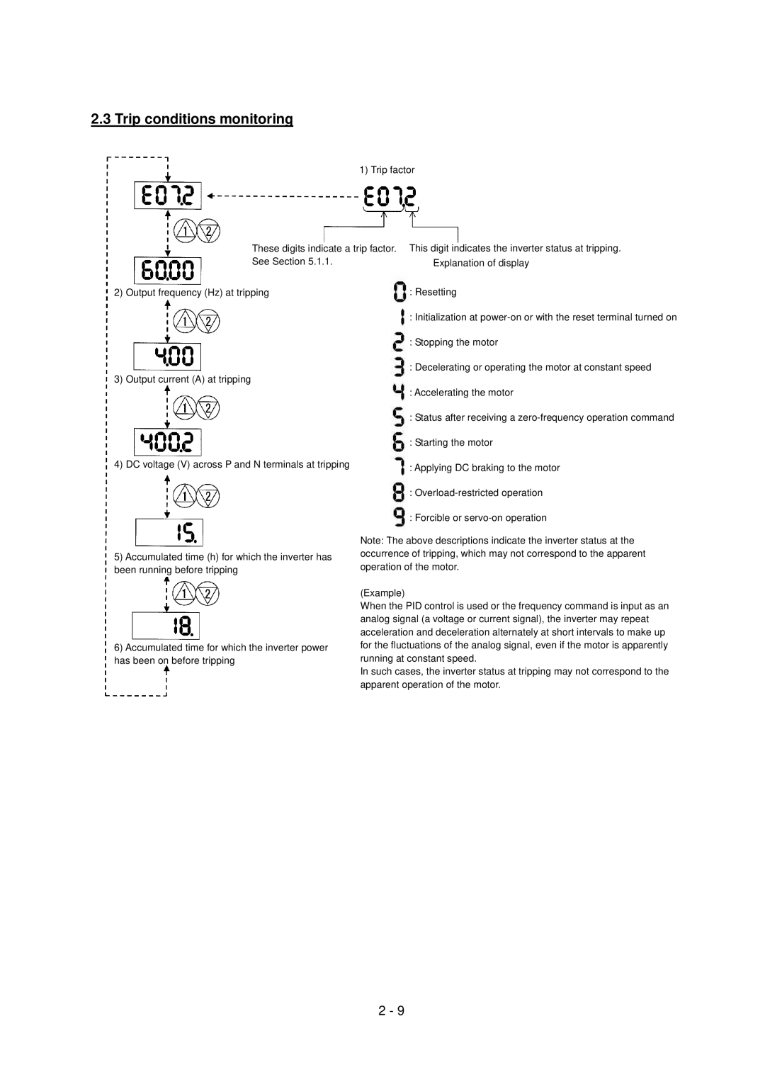
1) Trip factor
These digits indicate a trip factor. This digit indicates the inverter status at tripping.
See Section 5.1.1. |
|
| Explanation of display | |
2) Output frequency (Hz) at tripping |
|
| : Resetting | |
|
|
| : Initialization at | |
|
|
| : Stopping the motor | |
3) Output current (A) at tripping |
|
| : Decelerating or operating the motor at constant speed | |
|
|
| ||
|
|
| : Accelerating the motor | |
|
|
| : Status after receiving a | |
|
|
| : Starting the motor | |
4) DC voltage (V) across P and N terminals at tripping |
|
| : Applying DC braking to the motor | |
|
|
| ||
|
|
| : | |
|
|
| : Forcible or | |
| Note: The above descriptions indicate the inverter status at the | |||
5) Accumulated time (h) for which the inverter has | occurrence of tripping, which may not correspond to the apparent | |||
operation of the motor. | ||||
been running before tripping | ||||
| (Example) | |||
| When the PID control is used or the frequency command is input as an | |||
| analog signal (a voltage or current signal), the inverter may repeat | |||
| acceleration and deceleration alternately at short intervals to make up | |||
6) Accumulated time for which the inverter power | for the fluctuations of the analog signal, even if the motor is apparently | |||
has been on before tripping | running at constant speed. | |||
| In such cases, the inverter status at tripping may not correspond to the | |||
| apparent operation of the motor. | |||
2 - 9